Q235具有较高的强度、塑性和韧性以及较好的可焊性, 成本低廉, 而且焊接时一般不需要进行预热、控制层间温度、后期热处理等工序,具备良好的焊接特性,因此被广泛应用于工程中。多层多道焊接方式具有热输入量小、有效降低缺陷概率等优点[1-2],在中厚板焊接结构件中得到了广泛应用.但中厚板多层多道焊接过程是一个涉及传热、力学、冶金等多物理场耦合的复杂过程[3-5],在其焊接过程中,母材和焊缝金属均会经历多次焊接热循环,使得每道焊缝的温度场、热应力场的分布变得非常复杂.同时,在多层多道焊接过程中,由于层-层、道-道、层-道等之间相互影响,导致工件形成极大的温度梯度,从而产生极不均匀的焊接热应力和残余应力,使得工件发生较大的角变形,最终影响构件装配和使用[6-7].
为减小中厚板多层多道焊接过程中的角变形,揭示焊接角变形机理,近年来,国内外许多研究机构针对焊接过程中温度-应力、温度-流场以及温度-应力-流场等相关物理场开展了耦合场数值计算研究[8-9].Chong等[10]模拟了多层多道焊接过程中引起的初始应力对焊接过程中残余应力对焊接质量的影响;杜宝帅等[11]通过考虑坡口形式对热输入分布的影响以及焊缝横断面形状的特征分布,利用ANSYS软件对超细晶钢多层多道焊温度和残余应力模拟运算.Von-mises等效应力在起弧及熄弧端较大,达到屈服强度,其余位置均小于屈服强度.但关于温度场和热应力耦合场对工件角变形方面的研究鲜有报道[12].
文中采用COMSOL建立了温度场和热应力耦合场模型,研究了温度和热应力耦合场对角变形的影响规律,为后续控制、调整和减少工件的焊接角变形提供理论依据,具有非常重要的学术价值和实用意义[13-14].
1 温度和热应力耦合场模拟 1.1 热源模型及工艺参数在中厚板V型坡口多层多道焊接过程中,电弧的加热区域会同时覆盖到V型坡口的两侧区域,电弧热流分布模式符合体积热源特征,因此文中热源模型选择双椭球体热源模型.假设前后半椭球的热输入份额分别为ff和fr,且ff + fr=2,其热源模型公式为:
前半椭球:
| $ {q_f} = \frac{{6\sqrt 3 Q{f_{\rm{f}}}}}{{{\rm{ \mathsf{ π} }}ab{c_{\rm{f}}}\sqrt {\rm{ \mathsf{ π} }} }}{\rm{exp}}\left[ { - 3\left( {\frac{{{x^2}}}{{{a^2}}} + \frac{{{y^2}}}{{{b^2}}} + \frac{{{z^2}}}{{c_{\rm{f}}^2}}} \right)} \right]; $ | (1) |
后半椭球:
| $ {q_r} = \frac{{6\sqrt 3 Q{f_{\rm{r}}}}}{{{\rm{ \mathsf{ π} }}ab{c_{\rm{r}}}\sqrt {\rm{ \mathsf{ π} }} }}{\rm{exp}}\left[ { - 3\left( {\frac{{{x^2}}}{{{a^2}}} + \frac{{{y^2}}}{{{b^2}}} + \frac{{{z^2}}}{{c_{\rm{r}}^2}}} \right)} \right]. $ | (2) |
式中:qf、qr分别是前后半椭球的热流密度的体积分布;a、b、cf、cr是热流的体积分布参数;Q为焊接热输入的有效功率;x方向为焊接前进法线方向;y方向为焊接前进方向;z方向为焊缝厚度方向.
其热源移动方程为:
| $ \begin{array}{l} {\text{if}}(V\left( t \right)>0, ({\rm{if}}(x>0, {q_f}^*((x, \left( {y - 5} \right)t, z + \\ h)), {q_r}^*\left( {\left( {x, \left( {y - 5} \right)t, z + h} \right)} \right), M{\left( t \right)^*}(x, (y - \\ 5{)^*}t, z + h)). \end{array} $ | (3) |
式中:V(t)为方波方程;M(t)为方波函数;h为热源距工件上表面距离.
| $ \begin{array}{l} V\left( t \right) = \frac{1}{2} + \frac{2}{{\rm{ \mathsf{ π} }}}{\rm{(sin \mathsf{ π} }}t + \frac{1}{3}{\rm{sin3 \mathsf{ π} }}t + \frac{1}{5}{\rm{sin5 \mathsf{ π} }}t + \\ \;\;\;\;\;\;\; \ldots + \frac{1}{{2n - 1}}{\rm{sin}}(\left( {2n - 1} \right){\rm{ \mathsf{ π} }}t){\rm{ }}, \end{array} $ | (4) |
| $ \begin{array}{l} M\left( t \right) = \frac{1}{2} + \frac{2}{{\rm{ \mathsf{ π} }}}{\rm{(cos \mathsf{ π} }}t + \frac{1}{3}{\rm{cos3 \mathsf{ π} }}t + \frac{1}{5}{\rm{cos5 \mathsf{ π} }}t + \\ \;\;\;\;\;\;\; \ldots + \frac{1}{{2n - 1}}{\rm{cos}}(\left( {2n - 1} \right){\rm{ \mathsf{ π} }}t). \end{array} $ | (5) |
实验采用的工件材料型号为Q235,焊丝材料型号为ER50-6.采用多层多道焊焊接方法,焊接过程中,环境温度设定为295.15 K,焊件熔点1 825.15 K,焊丝熔点575.15 K,有效传热率(η)为0.65.其余焊接工艺参数见表 1.
| 表 1 焊接工艺参数 Table 1 Technological parameter of welding |
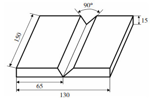
待焊工件选用长150 mm、宽65 mm、厚15 mm的单边V型坡口,两板对接所构成的V型坡口角度为90°,其结构示意图如图 1所示.
|
图 1 待焊工件示意图(mm) Fig.1 Schematic of the work piece to be welded |
依据中厚板多层多道焊V型坡口型式及焊道位置和数量,建立待焊工件的几何模型.焊接过程中分5层填满坡口,其实际焊道焊接示意图如图 2(a)所示.为便于焊接顺序的分析和仿真模型的建立,根据多层多道焊路径自动规划对V型坡口焊缝填充焊道截面进行一定的优化简化[15].将第1层焊道简化成三角形,将其余4层简化成矩形和直角梯形,简化后的V型坡口焊缝填充焊道截面示意图如图 2(b)所示.

|
图 2 焊道截面示意图 Fig.2 Schematic of weld cross section: (a) schematic diagram of actual welding section; (b) simplified schematic diagram of welding section |
试验过程中,母材和焊丝的熔化会形成熔池,进而对焊缝进行填充.COMSOL平台无法真实描述焊丝和焊缝金属填充焊缝的过程,因此,几何建模时采用生死单元技术模拟焊接过程中焊丝与母材随着焊枪的移动而熔化形成熔池的过程.
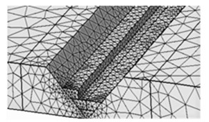
仿真过程中需要对焊件进行网格划分,在距离焊缝和热源比较近的区域,由于温度梯度和应力梯度变化幅度较大,需要将此部分区域的网格进行细致划分;而在距离焊缝和热源比较远的区域,温度梯度和应力梯度的变化较小,这部分区域的网格应进行标准划分.这样不仅大大缩短了仿真计算时间,而且还使仿真结果更加贴近实际的焊接效果.网格划分后模型如图 3所示.
|
图 3 网格划分 Fig.3 Mesh generation |
对于边界条件,在焊件上下表面和周围环境之间的热交换过程中,距离焊缝和热源较近的部分施加热辐射和热通量,距离两者较远的部分施加热对流.为防止工件移动以及便于观测工件在多层多道焊温度场和热应力耦合场作用下另一侧纵向(焊接方向)、横向(垂直于焊接方向)、厚度方向的角变形量,因此,只在工件的一侧施加固定约束.
2 温度和热应力耦合场分析基于COMSOL平台对多层多道焊温度场、热应力场计算结果见图 4, 可知:温度场和热应力场一一对应,热应力随着温度升高而变大,且两者保持一致的发展趋势,角变形也随着焊道增加而增大.

|
图 4 平板多层多道焊温度场、应力场计算结果 Fig.4 Simulation results of multi-layer multi-pass plates welding in stress field and temperature field: (a)first-layer temperature field; (b)third-layer temperature field; (c)fifth-layer temperature field; (d)first-layer stress field; (e)third-layer stress field; (f)fifth-layer stress field; (g)first-layer deformation; (h)third-layer deformation; (i)fifth-layer deformation |
以第1、3、5层温度场、热应力场以及角变形为例进行分析.第1层焊缝为打底焊,为防止热输入过高将其熔透,故设置较小的电流、电压,因此第1层焊缝表面温度和热应力相对较低,温度约为1 400 K,热应力约为500 MPa,但由于焊道处于角变形根部,因此角变形量较大;而在第3层和第5层焊接过程中,由于热循环和焊接电流、电压的增大,工件整体温度和热应力都有所增加,同时第3层和第5层的热循环影响区域相比于第1层变大,由于距离角变形根部较远,角变形量较小,但角变形量随着焊道的增加而增大.
图 4(b)、(e)、(h)为第3层焊缝温度场和应力场,由计算结果可知,第3层温度场和应力场的热循环影响范围最大,在工件中靠近热源的区域温度达到峰值1 901 K, 热应力达到峰值539 MPa,超过了工件的熔点.而对于第5层焊道,如图 4(c)、(f)、(i)所示,虽然其温度和热应力的峰值较高,但因其距下表面较远而距上表面较近,大部分热循环影响区域在上表面和第3、4层焊道附近区域.故第5层焊道对上表面的热循环影响区域较大,而对于第1、2层焊道热循环影响较弱,因此,其对工件根部的角变形影响最小.
为探究温度和热应力耦合场对工件角变形量的影响,需要对工件横向、纵向、厚度方向以及层-层间温度场和热应力场变化规律进行研究.
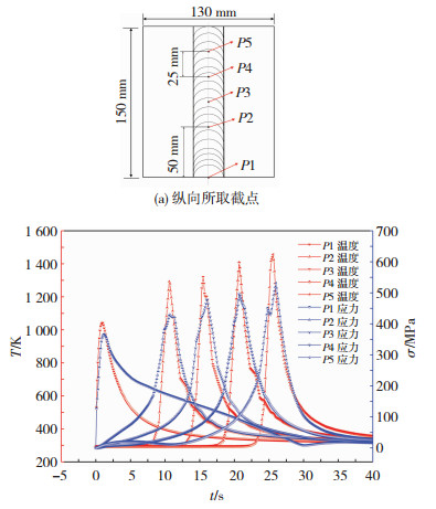
图 5为第1层纵向(焊接方向)不同点处温度场、热应力场热循环曲线.随着焊接热源的移动,温度和热应力随时间不断变化.在起始点的位置,温度和热应力比较低,温度约为1 035 K,热应力约为357 MPa,这主要是因为起点位置电弧不稳定,焊接速度快而导致的;随着热源的移动,焊缝截点处温度和热应力也呈现增长的趋势,其中最大值达到了1 400 K、500 MPa.图 5(a)为选取焊缝纵向的5个点(P1、P2…P5),随着焊接热源靠近选取的截点时,该截点温度、热应力迅速上升达到峰值,当热源远离时,该点的温度和热应力会逐渐下降直至平稳.但整体焊缝区域温度、热应力都呈现上升的趋势,当到达30 s焊接结束时,工件的温度和热应力开始逐渐下降,但是由于热循环的存在,热应力下降速率相比于温度较为缓慢.
|
图 5 第1层温度场、热应力场热循环曲线 Fig.5 Curve graph of thermal cycle in temperature field and thermal stress fields on the first layer |
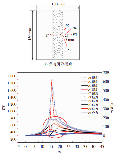
图 6为横向(垂直于焊接方向)不同点温度场、热应力场热循环曲线.图 6(a)垂直于焊接方向的5个截点(P1、P2…P5).当热源靠近截点时,该点的温度和热应力逐渐升高,当热源到达该点的时候, 温度和热应力都分别达到了峰值,当热源远离时,温度和热应力逐渐降低直至平稳.但是,随着与焊缝中心距离的增大,温度和热应力也会变得越来越小;焊缝中心点的温度峰值达到了1 901 K,热应力达到了539 MPa,而距离焊缝5 mm的截点的温度和热应力峰值分别为801 K、325 MPa;当距离焊缝20 mm时,温度场和热应力场几乎不变;距离焊缝中心点越远,温度和热应力的峰值越小,热循环影响越弱.
|
图 6 第3层温度场和热应力场热循环曲线 Fig.6 Curve graph of thermal cycle in temperature field and thermal stress fields on the third layer |
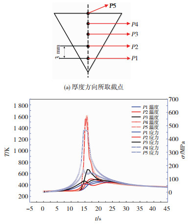
图 7(a)为第5层不同点(P1、P2…P5)温度场、热应力场热循环曲线(厚度方向).如图 7所示在厚度方向上,随着与焊缝中心的距离不断增加,温度和热应力的峰值越来越小,热影响区域也越小.在P1、P2处截点温度和热应力的峰值比较大,而距离焊缝中心9 mm截点处的温度、热应力峰值仅有666 K、95.3 MPa.距焊缝中心的距离越大,焊接热影响区越小,热循环影响越弱.第5层温度场和热应力对工件下表面以及第1和2层的热影响较小.因此,温度和热应力在厚度方向上热影响较小.焊缝成形以及焊接角变形仅影响当前和距离较近的焊层,但温度和热应力的整体上升以及下降趋势始终保持一致.
|
图 7 第5层温度场、热应力场热循环曲线 Fig.7 Curve graph of thermal cycle in temperature field and thermal stress fields on the fifth layer |
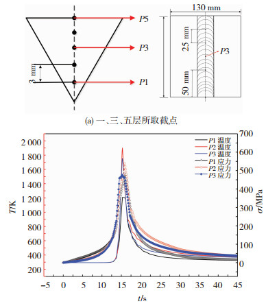
图 8为有限元分析得到的为1、3、5层所取裁点以及相对应温度场和热应力场曲线图.
|
图 8 第一、三、五层温度场和热应力场热循环曲线 Fig.8 Curve graph of thermal cycle in temperature field and thermal stress fields on the first, third, and fifth layer |
在不同层不同焊道上,第1层打底焊因焊接工艺参数较小,因此在焊接过程中温度场和应力场较低,但由于位于坡口根部,因此角变形最大;而第3层第2道由于第2层和第3层第1道热循环的存在以及热量扩散面较小,温度和热应力整体增加,达到峰值:温度1 901 K,热应力539 MPa, 对角变形的影响较大;而第5层第3道,由于扩散面的增加和层-层、道-道之间的相互影响,整体温度有所下降,角变形量较小;但温度和热应力保持相同发展的趋势.
3 试验验证由于焊接过程中,焊接热输入的大小决定温度高低,继而影响热应力变化,最终导致工件的热变形.利用机器人焊接系统试验平台对其进行试验验证,其中机器人采用的是ABB的1410型机器人,电焊机使用的是福尼斯4000R型焊机,保护气为体积分数80%Ar+20%CO2.焊接送丝速度除第1层为3.7 m/min外,其余均为5 m/min.其他实际焊接工艺参数同仿真预定参数保持一致,如表 1所示.
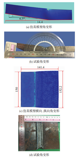
平板V型坡口在温度-热应力耦合场的作用下工件发生角变形,如图 9所示.
|
图 9 角变形试验 Fig.9 Experiment of angle deformation: (a) angle deformation of simulation model; (b) test of angle deformation; (c)transverse and longitudinal angle deformation of the simulation model; (d) test of angle deformation |
随着热源的移动,焊接温度和热应力呈现先上升后下降的趋势.当热源靠近截点位置时,该截点的温度与应力迅速上升;当热源远离该截点时,温度迅速下降直至平稳,而热应力由于热循环的存在,下降速度相对较为缓慢.数值模拟计算结果和实际试验结果对比显示,工件在横向、纵向以及厚度方向都发生了一定的形变.仿真模型横向计算值为140.4 mm,试验值为140.2 mm,误差为1.41%;仿真模型纵向计算值为152.2 mm,试验值为152.0 mm,误差为0.13%;仿真模型厚度方向计算值为15.2 mm,试验值为15.1 mm,误差为0.66%;角变形理论值为B=6.5°,试验值为B=6.63°, 误差为0.196%.
由此可知,试验值与计算值两者吻合情况良好.根据数值模拟计算结果和试验结果可知:工件在横向被拉升10.4 mm,纵向伸长2.2 mm,厚度增加了0.1 mm.因此,在平板V型坡口多层多道焊中温度-热应力耦合场主要作用于工件的横向和纵向,而对厚度方向影响较小.
4 结论1) 建立了中厚板V型坡口多层多道焊温度和热应力耦合场的数学模型,对V型坡口填充焊道截面简化进行优化,并且对多层多道焊温度场、热应力场以及工件的角变形进行了数值计算和定量分析.结果表明, 热应力和温度几乎保持一致的变化趋势.
2) 数值模拟计算值与试验值基本吻合.温度场和热应力耦合场主要作用于工件的横向和纵向,而对厚度方向影响较小.
| [1] |
危文灏, 贠超, 宋德政, 等. 机器人多层多道焊接的路径规划[J]. 机器人, 2014, 36(3): 257-262. WEI Wenhao, YUN Chao, SONG Dezheng, et al. Path planning for robotic multi-path/multi-layer welding[J]. Transactions of the China Welding Inslitution, 2014, 36(3): 257-262. DOI:10.3724/SP.J.1218.2014.00257 |
| [2] |
王丽, 张树海, 李启发, 等. 不锈钢/钢复合管水压爆炸焊接制造的数值模拟[J]. 材料科学与工艺, 2018, 26(1): 69-74. WANG Li, ZHANG Shuhai, LI Qifa, et al. Numerical simulation of stainless steel/steel composite tube manufactured by hydraulic explosion welding[J]. Materials Science and Technology, 2018, 26(1): 69-74. DOI:10.11951/j.issn.1005-0299.20170118 |
| [3] |
PARK W D, CHI B B, JI H K. Effects of heat input and bead generation methods on finite element analysis of cylindrical multi-pass welding process of metals[J]. Transactions of the Korean Society of Mechanical Engineers-A, 2017, 41(6): 455-467. |
| [4] |
朱玉斌, 郭永环, 郭妍, 等. V型坡口多层多道焊温度场数值模拟[J]. 热加工工艺, 2017(17): 207-209. ZHU Yubin, GUO Yonghuan, GUO Yan, et al. Numerical simulation of temperature field of multi-layerand multi-pass welding of V groove[J]. Rare Metals, 2017(17): 207-209. |
| [5] |
张志强, 荆洪阳, 徐连勇, 等. 双相不锈钢多层多道焊接接头微观组织表征[J]. 焊接学报, 2017, 38(5): 79-82. ZHANG Zhiqiang, JING Hongyang, XU Lianyong, et al. Microstructure characterization of duplex stainless steel multi-pass welded joint[J]. Transactions of the China Welding Inslitution, 2017, 38(5): 79-82. |
| [6] |
PARK J U, AN G, WOO W. The effect of initial stress induced during the steel manufacturing process on the welding residual stress in multi-pass butt welding[J]. International Journal of Naval Architecture & Ocean Engineering, 2018, 10(3): 129-140. |
| [7] |
蹤雪梅, 张贵芝, 黄松, 等. 多层多道焊接残余应力与变形三维数值模拟[J]. 电焊机, 2016, 46(3): 117-121. ZONG Xuemei, ZHANG Guizhi, HUANG Song, et al. 3-D simulation of welding residual stresses and distortion of the multi-pass welding[J]. Electric Welding Machine, 2016, 46(3): 117-121. |
| [8] |
KISAS ZÖA, TVMER M, KARAASLAN A. Effect of multipass welding on microstructural and mechanical properties of AISI 2205 duplex stainless steel[C]// International Iron & Steel Symposium. Karabuk-Turkey: [s.n.], 2017: 3-15.
|
| [9] |
QIN M, CHENG G, ZHANG Z, et al. Numerical simulation of temperature field and residual stress in multi-pass welds in 2.25Cr-1Mo-0.25V steel plate and comparison with experimental measurements[J]. American Society of Mechanical Engineers Pressure Vessels & Piping Division Pvp, 2007, V01BT01A033. |
| [10] |
CHOUNG J, NAMA J M, TAYYAR G T. Residual ultimate strength of a very large crude carrier considering probabilistic damage extents[J]. International Journal of Naval Architecture & Ocean Engineering, 2014, 6(1): 14-26. |
| [11] |
杜宝帅, 马学周, 张忠文, 等. 超细晶Q460钢多层多道焊接头残余应力的数值模拟[J]. 焊接学报, 2014, 35(2): 42-46. DU Baoshuai, MA Xuezhou, ZHANG Zhongwen, et al. Numerical simulation of residual stresses in multilayer multipass weld joints[J]. Transactions of the China Welding Inslitution, 2014, 35(2): 42-46. |
| [12] |
王学, 胡磊, 陈东旭, 等. 马氏体相变对9%Cr热强钢管道多道焊接头残余应力演化的影响[J]. 金属学报, 2017, 53(7): 888-896. WANG Xue, HU Lei, CHEN Dongxu, et al. Effect of martensitic transformation on stress evolution in multi-pass butt-welded 9%Cr[J]. Acta Metallurgica Sinica, 2017, 53(7): 888-896. DOI:10.11900/0412.1961.2017.00034 |
| [13] |
彭杏娜, 彭云, 彭先宽, 等. 多层多道TIG焊对高强钢焊缝组织和韧性的影响[J]. 机械工程学报, 2017, 53(18): 106-112. PENG Xingna, PENG Yun, PENG Xiankuan, et al. Influence of multi-layer and multi-pass TIG welding process on the highstrength weld metal microstructure and toughness[J]. Journal of Mechanical Engineering, 2017, 53(18): 106-112. DOI:10.3901/JME.2017.18.106 |
| [14] |
PARK J U, AN G B, WAN C W, et al. Residual stress measurement in an extra thickmulti-pass weld using initial stress integrated inherent strain method[J]. Marine Structures, 2014, 39(12): 424-437. |
| [15] |
杨光远.多层多道焊路径自动规划及双机器人协调研究[D].哈尔滨: 哈尔滨工业大学, 2008. YANG Guangyuan. Automatic path planning of multi-pass welding and reserch on double robotic coordination[D].Harbin: Harbin Institute of Technology, 2008. |
 2019, Vol. 27


