2. School of Science, Changzhou Institute of Technology, Changzhou 213032, Jiangsu, China;
3. School of Automotive Engineering, Changzhou Institute of Technology, Changzhou 213032, Jiangsu, China
Thin-walled tubes are widely used in many engineering fields due to their excellent mechanical properties with light weight. Therefore, the thin-walled tubes and related composite structures are extensively applied in both macro- and micro-scaled engineering and technology such as automobile, aerospace, thermal engineering, medicine, environment protection and micro-electro-mechanical technology[1-6]. For example, in terms of buckling of thin-walled tubes that will lead to a disaster, Xu et al.[3] developed a new technology on improving buckling resistance in which the local surface nanocrystallization was adopted to increase the critical loads of thin-walled structures. The optimal design of local surface nanocrystallization was established by estimating the ultimate buckling deformation. In addition to individual thin-walled tubes, the buckling or thermal buckling of micro-thin-walled tubes such as carbon nanotube reinforced composite structures has also received more and more research attention[7]. The research on thin-walled tubes and filled thin-walled tubes has been one of the hotspots over the past several decades[8]. One reason is that they demonstrate an excellent load-carrying capacity and energy-absorbing property as compared with other constructions with identical mass[9-10]. It is well known the bending deformation frequently takes place when a transverse load acts on the engineering structures especially on the thin-walled tubular members[5, 8-10]. Kim and Reid[11] first summarized some existing methods of collapse analyses for thin-walled tubes and then developed an admissible and completely analytical solution for bending collapse of thin-walled tubes with a rectangular section, and it agrees well with experimental results reported. Chang et al.[12] showed effects of the mean moment on the response and collapse of circular thin-walled tubes subjected to cyclic bending via both experimental and theoretical approaches, and proposed an empirical formulation to determine the relation between the moment range and the number of cycles necessary to produce buckling for thin-walled tubes since the buckling of thin-walled structures has attracted increasing research interest in recent years. Subsequently, Zhang et al.[13] investigated the bending collapse behaviors of thin-walled square tubes with different thickness for flanges and web plates, and found that placing more materials in the webs and less in flanges is an effective strategy to enhance the bending resistance. Considering the complicated deformation characteristics and influential factors, Huang and Zhang[14] conducted a detailed investigation on the bending collapse of rectangular tubes by both experimental tests and numerical simulations. Bigdeli and Nouri[15] presented systematically the property and optimization of aluminum thin-walled cylindrical energy absorber. The response surface method was adopted and some numerical, experimental and statistical analyses were carried out. Their work implied linear or nonlinear relationships between thickness, height, length, initial peak crushing force and energy absorption per length, respectively. Asanjarani et al.[16] examined the mechanical characteristics and energy absorption behaviors of straight and grooved tapered thin-walled tubes with different cross-section shapes including circle, ellipse, square, rectangle, hexagon, and octagon, and it has shown that mechanical characteristics may be improved via a geometry modification. After that, Jishi et al.[17] paid attention to tubular sandwich structures in which small diameter tubes were fixed onto metallic surface, and then explored their excellent energy-absorbing characteristics, based on which the tubular sandwich structures are expected to be useful in the environment with extreme dynamic loads.
However, the tubes with thin walls are apt to generate local indentation which would largely decrease their global loading capacity. It is more obvious for thin-walled tubes which are subjected to a concentrated force. An effective attempt is filling a lightweight material such as metallic foams into the thin-walled tube to resist the local indentation and keep its global load-carrying capacity[18-20]. Similar ideas can also be used to improve the bending crashworthiness of plates and shells, so as to construct a popular sandwich energy absorption structure[21-24]. Therefore, it is necessary to study the mechanical properties of such a composite structure namely thin-walled tubes filled with metallic foams, including foam filling style, filling amount, design of cross section and so on[25-27]. For example, Santosa et al.[28] examined the bending response of thin-walled square tubes filled with aluminum foams using a nonlinear finite element code, and concluded that the filler restrains inward deformation at a compressive flange. Consequently, it causes a considerable increase of the bending resistance and thus reduces the structural bending deformation. Chen et al.[29] studied the bending collapse of thin-walled square tubes filled with aluminum foams or honeycombs, and derived the moment-rotation relation to optimize the crashworthiness of the filled members. Li and Lu[30] performed a comparative study on the bending crashworthiness characteristics of different tubular structures filled with aluminum foams, and discovered that the energy-absorbing performance of foam-filled double tubes are superior to that of conventional empty or foam-filled single tubes. Gao and Liao[31] designed a novel thin-walled structure filled with double arrowed auxetic members and subsequently revealed its unique mechanical properties especially the energy absorption characteristics. A gradient configuration was proposed and the theoretical model was validated by numerical simulations. Xie et al.[32] presented the bending crashworthiness of thin-walled tubes with multi-cell and double-tube configurations based on the three-point bending simulation.
As aforementioned, filling lightweight materials into thin-walled constructions has been proved to be an efficient way to improve the bending resistance. Nevertheless, lightweight is one of the eternal goals of engineering structures. To furthermore decrease the structural mass, partially filling along the axial direction of the tubes is an effective method. Santosa et al.[28] and Chen et al.[29] found that the thin-walled tubes partially filled with foams show high anti-bending capacity, and the effective filling length is proposed to determine the foam filling length required. However, for the thin-walled tubes partially filled with foams along the axial direction, the filler would be out of action once the impact acts on the regions without the filler. Moreover, bending behaviors of another kind of partially foam-filled sections named foam-filled double tubes also attract the research attention of some investigators[33]. The results indicated that foam-filled double tubes show higher energy absorbing capacity in comparison with the conventional foam-filled single tubes in the same total mass situation.
Nevertheless, it also needs to be emphasized that this article considers partially filled square tubes. Previous experimental studies have focused on fully filled circular tubes. Due to limitations in specimen preparations and experimental equipments, it is difficult to directly carry out experimental verification in this article. Moreover, there have been few experimental results in previous literature which are completely consistent with the present model for reference. In addition, finite element analysis or simulation has become a commonly used and reliable research method, and the calculation results are also widely adopted in this field.
In the present study, different cross-sectional configurations of thin-walled square tubes partially filled lightweight foams, named DC-PF and DT-PF respectively, are proposed and designed. Subsequently, their bending crashworthiness is examined via a three-point bending test in the framework of the finite element analysis software ABAQUS. Two mechanical indicators CLE and SEA are introduced to show quantitatively the influence mechanism of physical properties of foams on the bending crashworthiness of partially filled thin-walled square tubes. To this end, the empty and fully filled square tubes are used to compare with the analysis results of DC-PF and DT-PF, respectively. The numerical models were established, and three cases of square tubes with the ratios of width to wall thickness b/t=100, 50, 33 are modeled in detail. Some beneficial numerical results are obtained and discussed. The present research has practical reference significance for the design and optimization of thin-walled tubes partially filled with lightweight metallic foams used in various engineering structures.
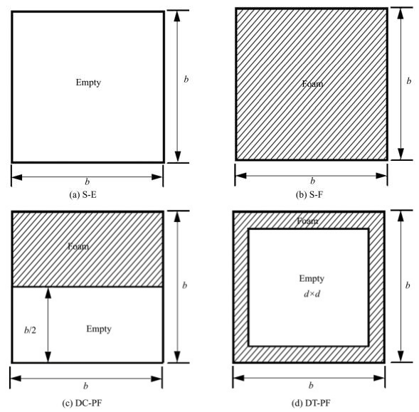
1 Structure and Test DesignsConsidering a thin-walled square tube with width b×b and wall thickness t, as shown in Fig. 1(a), it is often fully filled with lightweight foam material to improve load-carrying capacity, as shown in Fig. 1 (b). When the empty square tube is partitioned by a transverse internal web, they will become a double-cell configuration. Previous research revealed that the inward deformation at the compressive flange is the key to result into the decrease of bending resistance of thin-walled constructions, so it is suggested to only fill the upper cell with lightweight foams, as shown in Fig. 1(c). In addition, inserting a smaller square tube with width d×d into the tube and filling the clearing between the two tubes with lightweight foams, the foam-filled double tube comes into being, as demonstrated in Fig. 1(d). All the four configurations are assumed to have the same global width b and the same wall thickness t. Some notations are introduced for the sake of reference convenience. S-E refers to the single empty tube, and S-F represents its counterpart fully filled with lightweight foams. DC-PF and DT-PF denote double-cell tubes and double-tube tubes partially filled with foam, respectively.
|
Fig.1 Schematic of the presented cross sections of square tubes |
General three-point bending tests of the thin-walled square tubes with the above four cross-sections are suggested for the comparison of bending crashworthiness, as illustrated in Fig. 2. The side width of the square cross-section b is assigned 0.1 m, and the two bearings and the loading punch are supposed to be rigid cylinders with identical radius R=0.1 b=10 mm. The whole length of the tubes is L=10 b=1 m, and the span of the tubular beams between the two supports is s=8 b=0.8 m. The tubular walled thickness t is set as 1, 2 and 3 mm, which are denoted by b/t=100, 50 and 33, respectively. The internal tube width of DT-PF is assigned a constant value d=0.6 b=0.06 m.

|
Fig.2 Schematic of three-point bending tests of thin-walled square tubes |
2 Models and Results 2.1 Numerical Models
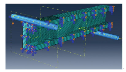
The finite element code ABAQUS/Explicit is employed to simulate the three-point bending behavior of the four structures mentioned above. Considering the symmetry of the bending tests, a quarter of models are established by assigning symmetric boundary conditions to save the computing time, as represented in Fig. 3.
|
Fig.3 A quarter of numerical model of three-point bending tests for the configuration DT-PF |
In the numerical models, the punch and the two bearings are simulated as 3D analytical rigid (not allowed any deformations), while the thin-walled tubes are modeled as 3D deformable shells. The foam fillers are modeled as 3D deformation solid. In addition, the dynamic, explicit procedure is executed, and the rigid punch moves downwards at an average velocity 0.1 m/s up to a displacement 0.1 m. The interaction between all of the possible contact surfaces is modeled using general contact with frictionless tangential behavior and hard normal behavior. Considering that the structural deformation would occur mainly in a short region across the midspan section, a length 0.3 m of the tubes are more finely meshed with an average size 3 mm, and other region approaching the two ends with 6 mm, as shown in Fig. 3. Similarly, the foams are meshed with sizes 5 mm and 10 mm, respectively. The reliability of the meshing sizes is verified through convergence analysis.
The tubular walls are assumed to be made of an elastic, ideally plastic metal material with density 7.8×10³ kg/m3, elastic modulus Es=200 GPa and flow stress σ0, s=600 MPa. The lightweight filler is postulated to be a metallic foam, and its solid cell wall is presumed to be the same as the tubular wall. In the ABAQUS material library, the Crushable Foam model well describes large strain behavior of metallic foams. According to previous studies, mechanical properties of metallic foam could be approximately depicted by the following Eqs. (1)-(5), where ρ, Ef, σp, εDinitial and εDfull represent its relative density, elastic Young's modulus, plateau stress, initial densification strain, and full densification strain, respectively. Additionally, ρf, ρs are the density of foam and its solid cell wall material, respectively. The symbols Es, σ0, s refer to the Young's modulus and flow stress of the solid cell wall material.
| $ \bar{\rho}=\rho_{\mathrm{f}} / \rho_{\mathrm{s}} $ | (1) |
| $ E_{\mathrm{f}}=E_{\mathrm{s}} \bar{\rho}^2 $ | (2) |
| $ \sigma_{\mathrm{p}}=\sigma_{0, \mathrm{~s}} \bar{\rho}^{3 / 2} $ | (3) |
| $ \varepsilon_{\mathrm{D}}^{\text {initial }}=1-1.4 \bar{\rho} $ | (4) |
| $ \varepsilon_{\mathrm{D}}^{\text {fill }}=1-\bar{\rho} $ | (5) |
The relations of Eqs. (2) and (4) are obtained from previous research Ref. [34] and Eq. (3) from Ref.[35]. The full densification strain expressed by Eq. (5) means that the foam is fully densified to its solid cell wall material. In the FE models, the nominal stain εnom under compressive deformation from Eqs. (4) and (5) needs be transformed into the true strain by Eq. (6). Five cases with different foam density are simulated in the present analysis, as shown in Table 1.
| $ \varepsilon_{\text {true }}=-\ln \left(1-\varepsilon_{\mathrm{nom}}\right) $ | (6) |
| Table 1 The mechanical properties of metallic foams employed in the present analysis |
On the other hand, three cases of wall thickness t=1 mm, 2 mm, 3 mm are computed here, and all parameters simulated in the present analysis are summarized in Table 2. For reference convenience, the following notations of the simulated cases are established based on these parameters. For example, S2-E represents the single empty tube with wall thickness 2 mm, and S2-F3 denotes the single tube with wall thickness 2 mm fully filled with the foam with relative density 0.2. DC2-PF3 signifies the double-cell configuration with wall thickness 2 mm partially filled with the foam with relative density 0.2, and so on.
| Table 2 All parameters simulated in the present analysis |
2.2 Typical Deformation Characteristics
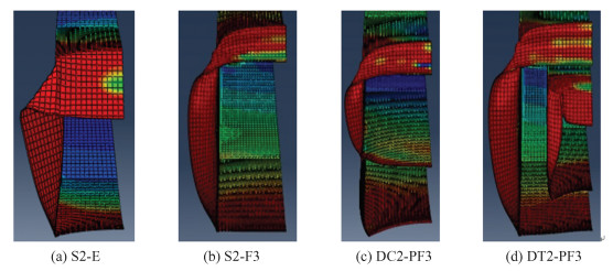
The typical deformation of the tubular wall for the above four configurations for the cases S2-E, S2-F3, DC2-PF3, DT2-PF3 is plotted in Fig. 4. It can be seen that S2-E generates large local indentation in a short region under the punch. The large local indentation results in an obvious decrease of the cross-sectional height and bending resistance. When the empty tube is filled with foam material, local indentation is well restrained, and the tubular deformation varies from local indentation to wrinkling. While the empty tube is reinforced with a transverse web and filled with foam material at the upper cell, the global flattening of the cross section and local indentation of the upper cell are both restricted, and load-carrying capacity evidently rises. As the empty tube is reinforced by an internal tube and filled with foam material in the clearing, both the global flattening of the cross section and local indentation of the upper compressive region are controlled, and bending resistance remains high level. It is noted that the external tube of DT-PF demonstrates much similar deformation to that of S-F at the cost of lighter total mass.
|
Fig.4 The typical deformation of tubular wall cross-sections at punch displacement 0.1 m |
2.3 Punch Forces Versus Displacement
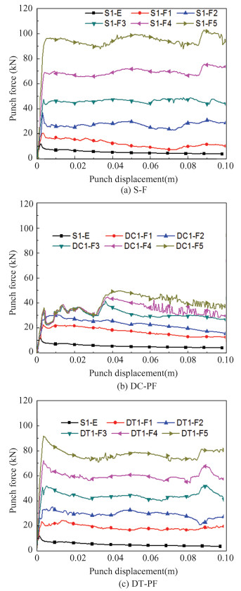
Fig. 5 shows the variation of punch forces with displacement for the case b/t=100, and wall thickness t=1 mm. It can be found that the foam filler significantly improves the load-carrying capacity as compared with the corresponding empty tube in Fig. 5(a). It is noted that some researchers have carried out experimental research on the simple foam filled thin-walled tubes. For example, Santosa et al.[28] experimentally investigated the bending behaviors of thin-walled columns filled with closed-cell aluminum foam. Chen et al.[29] presented the bending collapse of thin-walled beams filled with aluminum foam or aluminum honeycomb. Hanssen et al.[36] reported an experimental programme for the three-point bending of aluminium extrusions filled with aluminium foam subjected to a quasi-static loading condition. The simulation results obtained in this article are consistent with the experimental results aforementioned in terms of qualitative conclusions. However, compared with existing literature, this study considers a more complex structure, and there are currently no relevant experimental reports considering a configuration that is exactly the same as the one presented in this article termed as a thin-walled square tube partially filled with metallic foams. From Fig. 5, when the foam density is smaller, an initial peak force arises after elastic response. For the DC-PF configurations which is obviously an unaxisymmetric structure in finite element analysis, when the foam density is smaller, i.e. ρ=0.05 and 0.1, the force curves run with displacement similar to the fully filled tubes S-F. It is evidently different when the foam density is larger, i.e.ρ=0.2, 0.3 and 0.4, the three curves have almost the same initial running trend and subsequently diverge about at displacement 0.4 m. The reason is that large foam density considerably raises sectional bending resistance, the compressing collapse at the lower empty cell upon the two supports precedes the bending collapse under the punch. The compressing collapse at the lower empty cell upon the two supports has little relevance with the foam strength.
|
Fig.5 The variation of the punch forces with displacement for the case b/t=100 |
For the DT-PF configurations, the force curves display a similar tendency but a lower level compared with the S-F ones with the same foam density.
As the wall thickness increases, the load-carrying capacity generally improves, but the enhancing effect of the foam fillers decreares, as shown in Fig. 6 and Fig. 7. It is noted that the DC2-PF and DC3-PF configurations are dominated by bending collapse under the punch, with no obvious compressing collapse observed in the lower empty cell upon the two supports.
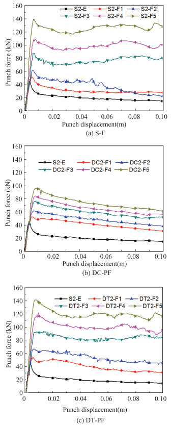
|
Fig.6 The variation of the punch forces with displacement for the case b/t=50 |
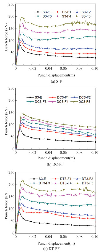
|
Fig.7 The variation of the punch forces with displacement for the case b/t=33 |
3 Discussion
Energy absorption is an important indicator in some engineering cases. Based on the principle of energy conservation, the structural energy absorption is equal to the work done by the external forces. For the case of three-point bending, only the punch force does work. So, the total energy absorption Et can be obtained by integrating the punch force P with its displacement δ up to the maximum value δmax, i.e.
| $ E_{\mathrm{t}}=\int_0^{\delta_{\max }} P \mathrm{~d} \delta $ | (7) |
The mean punch force Pm is another important indicator for an energy absorber, generally defined by the ratio of the total energy absorption Et to the maximum displacement δmax, as shown in Eq. (8),
| $ P_{\mathrm{m}}=E_{\mathrm{t}} / \delta_{\max } $ | (8) |
Moreover, too large peak reaction force perhaps does serious damage to the protected objects for an energy absorber. According to Zarei and Kr?ger[37], the crash load efficiency CLE is suggested to estimate the impact resistance for a given energy absorption. The definition of the CLE is the ratio of the mean load Pm to the maximum load Pmax expressed in Eq.(9).
| $ \mathrm{CLE}=P_{\mathrm{m}} / P_{\max } $ | (9) |
In addition, it is desirable to obtain the maximum energy absorption at the cost of light structure weight in most cases. The specific energy absorption SEA is proposed to evaluate energy absorbing capacity with certain structural mass, defined by the energy absorption per unit mass of the whole structures[38]:
| $ \mathrm{SEA}=E_{\mathrm{t}} / m_{\mathrm{t}} $ | (10) |
where mt is the total mass of the whole structures. For the foam-filled tubes, the total mass is the sum of the mass of tubular wall and that of the foam filler in Eq.(11).
| $ m_{\mathrm{t}}=\rho_{\text {wall }} A_{\text {wall }} L+\rho_{\text {foam }} A_{\text {foam }} L=\left(t l_{\text {wall }}+\bar{\rho} A_{\text {foam }}\right) \rho_{\text {wall }} L $ | (11) |
where L and lwall represent the tubular axial length and the total length of the sectional segments of the tubular wall, respectively. ρwall is the density of tubular wall material. For the cases S-F, when the foam density equals zero, the above formulation would be reduced to that of the cases S-E.
| $ A_{\mathrm{c}}=t l_{\text {wall }}+\bar{\rho} A_{\text {foam }} $ | (12) |
where parameter Ac, called characteristic mass here, dominates the total mass. For simplicity, in the following analysis, the specific energy absorption SEA is calculated as follows:
| $ \mathrm{SEA}=E_{\mathrm{t}} / A_{\mathrm{c}} $ | (13) |
Based on the numerical results as plotted in Figs. 5-7, the calculated results of the above mechanical indicators are listed in Tables 3-5, classified in terms of the parameter b/t.
| Table 3 The calculated results of the mechanical indices for the case b/t=100 |
| Table 4 The calculated results of the mechanical indices for the case b/t=50 |
| Table 5 The calculated results of the mechanical indices for the case b/t=33 |
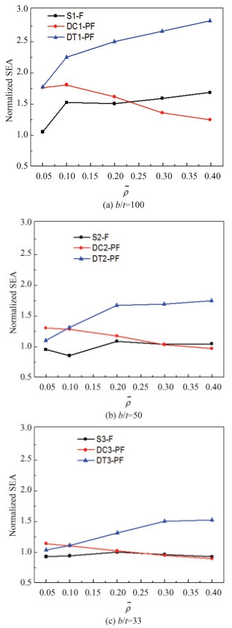
For intuitive comparison of bending crashworthiness among the above four configurations, four key mechanical indicators Pmax, Et, CLE and SEA are depicted in Figs. 8-11, respectively. Additionally, the indicators of the three configurations S-F, DC-PF and DT-PF are all normalized by that of S-E with the same wall thickness. For example, normalized Pmax denotes the Pmax of S-F, DC-PF and DT-PF divided by that of S-E, i.e.
| $ \text { Normalized } P_{\max }=\frac{P_{\max }(\mathrm{S}-\mathrm{F}, \mathrm{DC}-\mathrm{PF}, \mathrm{DT}-\mathrm{PF})}{P_{\max }(\mathrm{S}-\mathrm{E})} $ | (14) |
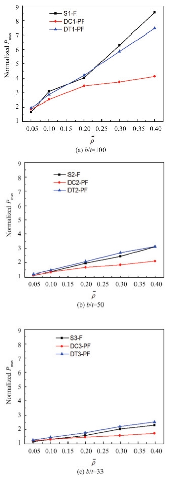
|
Fig.8 The maximum forces of the foam-filled tubes normalized by that of the single empty tube S-E for the different cases |
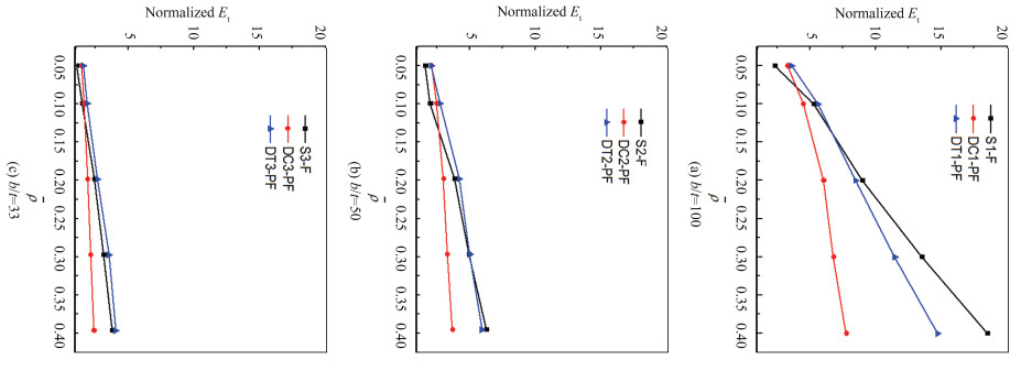
|
Fig.9 The total energy absorption of the foam-filled tubes normalized by that of the single empty tube S-E for the different cases |

|
Fig.10 The CLE of the foam-filled tubes normalized by that of the single empty tube S-E for the different cases |
|
Fig.11 The SEA of the foam-filled tubes normalized by that of the single empty tube S-E for different cases |
Regarding the theoretical analyses on bending crashworthiness of thin-walled square tubes partially filled with metallic foams, this article establishes a basic theoretical model with corresponding equations. Additionally, Hanssen et al.[36] developed some design formulae to predict the load bearing capacity of the foam filled beams that can also be referenced.
3.1 Pmax and EtFig. 8 gives the maximum forces of the foam-filled tubes normalized by that of the single empty tube S-E with identical wall thickness. It can be found that the foam filler largely raises the maximum forces, especially when the wall thickness is small. Furthermore, the maximum forces of the two configurations S-F and DT-PF show a similar linear increase with rising foam density. However, the DC-PF forces display lower maximum values.
Overall, the total energy absorption demonstrates variational characteristics similar to those of the maximum forces, as shown in Fig. 9. The two configurations S-F and DT-PF exhibit higher energy absorbing capacity than DC-PF when the relative density of foam filler is larger than about 0.1.
3.2 CLE and SEAFig. 10 presents the variation of the CLE of foam-filled tubes normalized by that of the single empty tube S-E with the same wall thickness. It can be observed that the CLE of the three foam-filled configurations is prominently larger than that of the configuration S-E, especially when the wall thickness is small. The CLE of the configurations S-F ascends with the relative density of foam filler till it reaches 0.2. When the relative density of foam filler extends to 0.2, the CLE of S-F almost keeps stable. For the case b/t=100, the CLE of the two configurations DC-PF and DT-PF is larger than that of S-F when the foam density is small. In contrast, the CLE of DC-PF and DT-PF is smaller than that of S-F. Futhermore, the CLE of DT-PF is greater than that of DC-PF. With the increase of wall thickness, the difference of the CLE among the three configurations becomes smaller. It is noted that the CLE of DT-PF keeps approximately stable when the relative density of the foam filler is larger than 0.2. There seems to exist a constant foam density threshold, beyond which the CLE of DT-PF achieves a maximum constant value.
Fig. 11 shows the variation of the SEA of the foam-filled tubes normalized by that of the single empty tube S-E with identical wall thickness. It can be seen that when the wall thickness is small, i.e. b/t=100, the SEA of S-F is remarkably larger than that of S-E. While the wall thickness is larger, i.e. b/t=50, 33, the SEA of S-F is almost identical to that of S-E. The SEA of DC-PF linearly decreases. The SEA of DT-PF extends considerably beyond the SEA of S-F and DC-PF, especially when the wall thickness is small. Moreover, the SEA of DT-PF remains approximately constant, when the foam density is greater than 0.1, 0.2 and 0.3 for the case b/t=100, 50 and 33 respectively. There appears to be a foam density threshold beyond which the SEA of DT-PF achieves a maximum constant value. However, the foam density threshold corresponding to the maximum SEA varies with the wall thickness.
4 ConclusionsThis study focus on the bending crashworthiness of thin-walled square tubes partially filled with metallic foams. The three-point bending behavior is simulated by employing the finite element ABAQUS/Explicit code, and three cases with the ratio of tube width to wall thickness b/t=100, 50, 33 are modeled, respectively. The bending crashworthiness of two configurations named DC-PF and DT-PF designed in the present study is examined using two key indicators CLE and SEA, and the corresponding results of empty and fully filled tubes are also presented to indicate the superiority of partially filled tubes over others. The numerical results show that the two configurations especially DT-PF reveals excellent bending crashworthiness. In addition, the CLE of DT-PF keeps approximately constant when the relative density of the foam filler is larger than 0.2. There is a threshold for the foam density, beyond which the CLE of DT-PF receives a peak value. Moreover, the SEA of DT-PF remains approximately a constant, when the foam density is greater than 0.1, 0.2 and 0.3 for the case b/t=100, 50 and 33 respectively. There exists another density threshold, and the SEA of DT-PF reaches a maximum when the threshold is exceeded. However, the foam density threshold related to the maximum SEA is not constant, which changes with respect to the wall thickness. The main contribution of the research is to propose the DC-PF and DT-PF configurations of thin-walled square tubes partially filled with metallic foams and demonstrate their advantages in the bending crashworthiness.
| [1] |
Wen T, Chen X. Investigation of guided external inversion of thin-walled round tube. Journal of Harbin Institute of Technology (New Series), 2012, 19(3): 38-42. (  0) 0) |
| [2] |
Wang H, Tang Y, Liu Z, et al. Machining deformation prediction of thin-walled part based on finite element analysis. Journal of Harbin Institute of Technology(New Series), 2015, 22(4): 47-54. DOI:10.11916/j.issn.1005-9113.2015.04.006 (  0) 0) |
| [3] |
Xu X, Zhao Z, Zhou Z, et al. Local surface nanocrystallization for buckling-resistant thin-walled structures. International of Journal of Mechanics and Materials in Design, 2020, 16: 693-705. DOI:10.1007/s10999-020-09497-8 (  0) 0) |
| [4] |
Hu W P, Huai Y L, Xu M B, et al. Mechanoelectrical flexible hub-beam model of ionic-type solvent-free nanofluids. Mechanical Systems and Signal Processing, 2021, 159: 107833. DOI:10.1016/j.ymssp.2021.107833 (  0) 0) |
| [5] |
Sebaey T A, Rajak D K, Mehboob H. Internally stiffened foam-filled carbon fiber reinforced composite tubes under impact loading for energy absorption applications. Composite Structures, 2021, 255: 112910. DOI:10.1016/j.compstruct.2020.112910 (  0) 0) |
| [6] |
Yan J, Yi S, Yuan X. Graphene and its composites: A review of recent advances and applications in logistics transportation. Packaging Technology Science, 2024, 37(4): 335-361. DOI:10.1002/pts.2795 (  0) 0) |
| [7] |
Li C, Zhu C X, Lim C W, et al. Nonlinear in-plane thermal buckling of rotationally restrained functionally graded carbon nanotube reinforced composite shallow arches under uniform radial loading. Applied Mathematics and Mechanics, 2022, 43(12): 1821-1840. DOI:10.1007/s10483-022-2917-7 (  0) 0) |
| [8] |
Lv J Y, Bai Z H, Du X P, et al. Crashworthiness design of 3D lattice-structure filled thin-walled tubes based on data mining. International Journal of Crashworthiness, 2023, 28(3): 435-448. DOI:10.1080/13588265.2022.2101306 (  0) 0) |
| [9] |
Xu X S, Zhao Z, Wang W, et al. A novel design of thin-walled energy absorption structures with local surface nanocrystallization. Thin-Walled Structures, 2021, 160: 107337. DOI:10.1016/j.tws.2020.107337 (  0) 0) |
| [10] |
Zhang H, Chang B X, Peng K F, et al. Anti-blast analysis and design of a sacrificial cladding with graded foam-filled tubes. Thin-Walled Structures, 2023, 182: 110313. DOI:10.1016/j.tws.2022.110313 (  0) 0) |
| [11] |
Kim T H, Reid S R. Bending collapse of thin-walled rectangular section columns. Computers & Structures, 2001, 79(20-21): 1897-1911. DOI:10.1016/S0045-7949(01)00089-X (  0) 0) |
| [12] |
Chang K H, Pan W F, Lee K L. Mean moment effect on circular thin-walled tubes under cyclic bending. Structural Engineering and Mechanics, 2008, 28(5): 495-514. DOI:10.12989/sem.2008.28.5.495 (  0) 0) |
| [13] |
Zhang X, Zhang H, Wang Z. Bending collapse of square tubes with variable thickness. International Journal of Mechanical Sciences, 2016, 106: 107-116. DOI:10.1016/j.ijmecsci.2015.12.006 (  0) 0) |
| [14] |
Huang Z X, Zhang X. Three-point bending collapse of thin-walled rectangular beams. International Journal of Mechanical Sciences, 2018, 144: 461-479. DOI:10.1016/j.ijmecsci.2018.06.001 (  0) 0) |
| [15] |
Bigdeli A, Nouri M D. Investigation of the numerical, experimental, statistical and optimization of thin-walled energy absorber with novel configuration using response surface method under axial loading. Journal of Sandwich Structures & Materials, 2020, 22(8): 2735-2767. DOI:10.1177/1099636218813196 (  0) 0) |
| [16] |
Asanjarani A, Mahdian A, Dibajian S H. Comparative analysis of energy absorption behavior of tapered and grooved thin-walled tubes with the various geometry of the cross section. Mech Adv Matl Struct, 2020, 27(8): 633-644. DOI:10.1080/15376494.2018.1488311 (  0) 0) |
| [17] |
Jishi H Z, Alia R A, Cantwell W J. The energy-absorbing characteristics of tubular sandwich structures. Journal of Sandwich Structures & Materials, 2022, 24(1): 742-762. DOI:10.1177/10996362211020457 (  0) 0) |
| [18] |
Jamsari M A, Kueh C, Gray-Stuart E M, et al. Modelling the impact of crushing on the strength performance of corrugated fibreboard. Packaging Technology Science, 2020, 33(4-5): 159-170. DOI:10.1002/pts.2494 (  0) 0) |
| [19] |
Zhao Y J, Cao Y F, Li L Y, et al. Experimental and finite element simulation study of the mechanical behaviors of aluminum foam-filled single/double tubes. Materials Research Express, 2023, 10(4): 046506. DOI:10.1088/2053-1591/acc2a4 (  0) 0) |
| [20] |
Altin M, Arici S. Investigation of the crushing performance of bio-inspired structure filled thin-walled hybrid aluminum tubes under axial loadings. Journal of the Faculty of Engineering and Architecture of Gazi University, 2024, 39(2): 1303-1313. DOI:10.17341/gazimmfd.1287380 (  0) 0) |
| [21] |
Stapleton S E, Adams D O. Core design for energy absorption in sandwich composites. Journal of Composite Materials, 2009, 43(2): 175-190. DOI:10.1177/0021998308099225 (  0) 0) |
| [22] |
Hou X H, Deng Z C, Zhang K. Dynamic crushing strength analysis of auxetic honeycombs. Acta Mechanica Solida Sinica, 2016, 29(5): 490-501. DOI:10.1016/S0894-9166(16)30267-1 (  0) 0) |
| [23] |
Bodaghi M, Serjouei A, Zolfagharian A, et al. Reversible energy absorbing meta-sandwiches by FDM 4D printing. International Journal of Mechanical Sciences, 2020, 173: 105451. DOI:10.1016/j.ijmecsci.2020.105451 (  0) 0) |
| [24] |
Khaire N, Tiwari G, Iqbal M A. Energy absorption characteristic of sandwich shell structure against conical and hemispherical nose projectile. Composite Structures, 2021, 258: 113396. DOI:10.1016/j.compstruct.2020.113396 (  0) 0) |
| [25] |
Hou S J, Li Q, Long S Y, et al. Crashworthiness design for foam filled thin-wall structures. Materials & Design, 2009, 30(6): 2024-2032. DOI:10.1016/j.matdes.2008.08.044 (  0) 0) |
| [26] |
Rogala M, Ferdynus M, Gawdzinska K, et al. The influence of different length aluminum foam filling on mechanical behavior of a square thin-walled column. Materials, 2021, 14(13): 3630. DOI:10.3390/ma14133630 (  0) 0) |
| [27] |
Ou X, Yao X H, Zhang R, et al. Nonlinear dynamic response analysis of cylindrical composite stiffened laminates based on the weak form quadrature element method. Composite Structures, 2018, 203: 446-457. DOI:10.1016/j.compstruct.2018.06.114 (  0) 0) |
| [28] |
Santosa S, Banhart J, Wierzbicki T. Experimental and numerical analyses of bending of foam-filled sections. Acta Mechanica, 2001, 148: 199-213. DOI:10.1007/BF01183678 (  0) 0) |
| [29] |
Chen W, Wierzbicki T, Santosa S. Bending collapse of thin-walled beams with ultralight filler: Numerical simulation and weight optimization. Acta Mechanica, 2002, 153: 183-206. DOI:10.1007/BF01177451 (  0) 0) |
| [30] |
Li Z B, Lu F Y. Bending resistance and energy-absorbing effectiveness of empty and foam-filled thin-walled tubes. Journal of Reinforced Plastics and Composites, 2015, 34(9): 761-768. DOI:10.1177/0731684415580329 (  0) 0) |
| [31] |
Gao Q, Liao W H. Energy absorption of thin walled tube filled with gradient auxetic structures-theory and simulation. International Journal of Mechanical Sciences, 2021, 201: 106475. DOI:10.1016/j.ijmecsci.2021.106475 (  0) 0) |
| [32] |
Xie Z X, Zhao Z X, Li C. Bending crashworthiness of thin-walled square tubes with multi-cell and double-tube cross-sections. Journal of Mechanical Science and Technology, 2021, 35(11): 4815-4823. DOI:10.1007/s12206-021-1001-6 (  0) 0) |
| [33] |
Guo L W, Yu J L. Dynamic bending response of double cylindrical tubes filled with aluminum foam. International Journal of Impact Engineering, 2011, 38: 85-94. DOI:10.1016/j.ijimpeng.2010.10.004 (  0) 0) |
| [34] |
Gibson L J, Ashby M F. Cellular Solids: Structure and Properties. Cambridge: Cambridge University Press, 1997. DOI:10.1017/CBO9781139878326
(  0) 0) |
| [35] |
Santosa S, Wierzbicki T. On the modeling of crush behavior of a closed-cell aluminum foam structure. Journal of Mechanics and Physics, 1998, 46(4): 645-669. DOI:10.1016/S0022-5096(97)00082-3 (  0) 0) |
| [36] |
Hanssen A G, Hopperstad O S, Langseth M. Bending of square aluminium extrusions with aluminium foam filler. Acta Mechanica, 2000, 142: 13-31. DOI:10.1007/BF01190010 (  0) 0) |
| [37] |
Zarei H R, Kröger M. Crashworthiness optimization of empty and filled aluminum crash boxes. International Journal of Crashworthiness, 2007, 12(3): 255-264. DOI:10.1080/13588260701441159 (  0) 0) |
| [38] |
Kim H S. New extruded multi-cell aluminum profile for maximum crash energy absorption and weight efficiency. Thin-Walled Structures, 2002, 40(4): 311-327. DOI:10.1016/S0263-8231(01)00069-6 (  0) 0) |
 2025, Vol. 32


