轴系的倾角回转误差对于机床上零件的加工精度,转台上的综合指向精度等关键技术指标有着重要影响,一些精密设备比如圆度仪、超精密机床等具有极高的回转精度要求,所以研究轴系倾角回转误差的测试评定方法有着重要的意义.其中,运用数学解析法描述各个轴系的倾角回转误差,并理清这些误差在系统中的传递过程是十分有意义的工作.国内外有很多评定轴系倾角回转误差的文献,文献[1-5]对轴系倾角回转误差的形成机理进行深入的剖析,
但均没有考虑轴系的一次谐振运动对轴系倾角回转误差的影响.文献[6]运用谐波分析的方法分析了轴系的倾角回转误差,并将影响回转精度的误差源归结为机械零件的制造误差,刚度不足引起的主轴轴系变形,以及零部件的装配误差,而没有对轴系的运动机理进行深入剖析.文献[7]在分析主轴误差信号的基础上,提出了有效分离安装偏心的方法,从而开发出一种测试结果与偏心无关的测试方法,但其同样没有细致分析轴系一次谐振运动.文献[8]提出一次分量中主轴一次误差运动应当分为“一次圆周误差运动”和“一次直线误差运动”两类.通过理论分析及传感器的改进,可消除一次分量而不影响测量精度.文献[9]从补偿运动机理角度分析了主轴回转误差与加工系统之间的动态相互作用.文献[10]设计和验证主轴运动误差分离技术具有亚纳米测量不确定度.文献[11]介绍了5自由度模型并分析了主轴轴承的加工误差,包括标准圆柱与轴的同心度误差.文献[12]介绍了在主轴回转误差测试过程中,如何消除标准圆柱的安装偏心误差.文献[13]介绍了消除实验数据中安装偏心的方法,测量系统实现了对高精度静压主轴回转误差和圆度的精确测量.文献[14]为了实现对超精密机床主轴回转误差的在线测试与评价,建立了纳米级在线测试与评价系统,并对该系统所采用的测试仪器“干扰抑制”数据处理与指标评价方法进行了研究.文献[15]说明主轴的回转误差受转速的影响,在空载高速运转状态下较明显,需根据实际零件加工精度需要,选择合适的加工速度.文献[16]以数控机床静压气体轴承的主轴系统为研究对象,设计了以静压气体轴承为主承载元件,主动磁轴承为辅助元件的主轴系统结构,利用主动磁轴承的可控性设计了回转误差的控制和补偿方法,提高了主轴的回转精度.文献[17]深入分析了测试数据中一次谐波项,得出了测试数据的一次谐波项是由两个垂直方向的相位相同一次谐波和相位正交的一次谐波叠加而成,相位正交的一次谐波为平面反射镜的安装偏差,而相同相位的一次谐波为轴系的一次谐振运动,前者在计算轴系倾角回转误差时应予以扣除,而后者为主轴运动本身所有,应当予以保留.但其没有进一步对轴系一次谐振运动进行分离处理,传统上的数据处理方法是把所有的一次谐波全部扣除掉,其实并不准确,因为它忽略了轴系一次谐振运动误差是轴系倾角回转误差的一部分.本文将以自准直仪-平面反射镜法测量轴系的倾角回转误差为例,将自准直仪的二维测量数据中的一次谐波进一步分解为轴系一次谐振运动所产生一次谐波和平面反射镜的安装误差所造成的一次谐波两个部分,并有效保留了轴系的一次谐振运动误差,从而更加准确地评估轴系的倾角回转误差.
1 轴系倾角回转误差的测试方法本文首先建立了与自准直仪、轴套、主轴和平面反射镜固联的坐标系,并考虑自准直仪和平面反射镜的安装误差,回转轴系相对于轴套的倾角回转误差,将推导平面反射镜坐标系与基准坐标系之间的姿态关系,进而导出自准直仪测量读数与上述安装误差以及轴系角位置的关系.
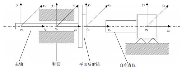
基准坐标系o0x0y0z0固联在自准直仪上,如图 1所示,o0z0与自准直仪的光轴一致,o0y0朝上,o0x0由右手定则确定.
|
图 1 自准直仪-平面反射镜法测量轴系的倾角回转误差 Figure 1 The measurement of wobble errors of the rotary axis system by autocollimator-reflected mirror method |
轴套坐标系o1x1y1z1的o1z1轴与o0z0轴的夹角为Δβ,它是自准直仪的安装误差,其中o1z1是轴系的平均回转轴线,轴套坐标系可以认为是绕基准坐标系的o0x0轴旋转Δβx,再绕o0y0轴旋转Δβy形成.轴套坐标系相对于基准坐标系的姿态矩阵为
| $ \mathit{\boldsymbol{T}}_1^0 = {\rm{Rot}}\left( {{x_0},\Delta {\beta _x}} \right){\rm{Rot}}\left( {{y_0},\Delta {\beta _y}} \right). $ |
主轴坐标系o2x2y2z2是在轴套坐标系o1x1y1z1的基础上绕轴o1x1旋转Δαx(γ),再绕轴o1y1旋转Δαy(γ),最后绕z轴旋转γ形成,Δαx(γ)、Δαy(γ)就是主轴轴系处于γ角位置时的二维倾角回转误差,主轴坐标系相对于轴套坐标系的姿态矩阵为
| $ \mathit{\boldsymbol{T}}_2^1 = {\rm{Rot}}\left( {{x_1},\Delta {\alpha _x}\left( \gamma \right)} \right){\rm{Rot}}\left( {{y_1},\Delta {\alpha _y}\left( \gamma \right)} \right){\rm{Rot}}\left( {{z_1},\gamma } \right). $ |
平面反射镜坐标系o3x3y3z3固联于平面反射镜上,它是考虑平面反射镜对于主轴几何轴线的二维垂直度Δβx2、Δβy2形成的.平面反射镜坐标系相对于主轴坐标系的姿态矩阵为
| $ \mathit{\boldsymbol{T}}_3^2 = {\rm{Rot}}\left( {{x_2},\Delta {\beta _{x2}}} \right){\rm{Rot}}\left( {{y_2},\Delta {\beta _{y2}}} \right). $ |
上述Rot()函数的定义见文献[1].根据坐标系之间的姿态传递关系,平面反射镜坐标系相对于基准坐标系的姿态矩阵为
| $ \mathit{\boldsymbol{T}}_3^0 = \mathit{\boldsymbol{T}}_1^0\mathit{\boldsymbol{T}}_2^1\mathit{\boldsymbol{T}}_3^2 = \left[ {\begin{array}{*{20}{c}} {{h_{11}}}&{{h_{12}}}&{{h_{13}}}\\ {{h_{21}}}&{{h_{22}}}&{{h_{23}}}\\ {{h_{31}}}&{{h_{32}}}&{{h_{33}}} \end{array}} \right]. $ |
根据姿态矩阵的定义,T30中的h13为o0x0轴与平面镜法线o3z3夹角的余弦,因为这个始终夹角接近90°,比如夹角为90°-Δθ,则cos(90°-Δθ)=sinΔθ≈Δθ,所以h13为o0x0轴与平面反射镜法线o3z3的垂直度,也是自准直仪在o0x0方向上的读数;同理分析T30中的h23就是自准直仪在o0y0方向上的读数.如果采取等间隔n点采样,取
| $ \begin{array}{l} {f_x}\left( {{\gamma _i}} \right) = {h_{13}} = \Delta {\beta _{y2}}\cos {\gamma _i} + \Delta {\beta _{x2}}\sin {\gamma _i} + \Delta {\beta _y} + \\ \;\;\;\;\;\;\;\;\;\;\;\;\;\Delta {\alpha _y}\left( {{\gamma _i}} \right), \end{array} $ | (1) |
| $ \begin{array}{l} {f_y}\left( {{\gamma _i}} \right) = {h_{23}} = \Delta {\beta _{y2}}\sin {\gamma _i} - \Delta {\beta _{x2}}\cos {\gamma _i} - \Delta {\beta _x} - \\ \;\;\;\;\;\;\;\;\;\;\;\;\;\Delta {\alpha _x}\left( {{\gamma _i}} \right). \end{array} $ | (2) |
由式(1)、(2)可以看出主轴轴线和自准直仪的光轴的平行度Δβx、Δβy表现为常数项,镜面与主轴轴线的垂直度Δβx2、Δβy2表现为一次谐波项.如果将这4个参数从自准直仪的二维测量读数中分离出来并加以扣除,即可得出轴系的倾角回转误差.
从式(1)、(2)可知平面反射镜安装误差Δβx2、Δβy2产生的一次谐波相位相差90°,但由于轴系本身存在一次谐振运动,也就是Δαx(γ)、Δαy(γ)中也含有一次谐波成分,将导致式(1)、(2)中fx(γi)、fy(γi)一次谐波的相位差不可能是90°,在实际的数据处理过程中是对它们进行分别处理,即将式(1)、(2)写成下式:
| $ {f_x}\left( {{\gamma _i}} \right) = \Delta {\theta _{xlc}}\cos {\gamma _i} + \Delta {\theta _{xls}}\sin {\gamma _i} + \overline {{f_x}} + \Delta {f_x}\left( {{\gamma _i}} \right), $ |
| $ {f_y}\left( {{\gamma _i}} \right) = \Delta {\theta _{ylc}}\cos {\gamma _i} + \Delta {\theta _{yls}}\sin {\gamma _i} + \overline {{f_y}} + \Delta {f_y}\left( {{\gamma _i}} \right), $ |
式中,Δfx(γi)、Δfy(γi)分别为x、y方向回转误差的二次及二次以上谐波.
平均值的求法:
| $ \overline {{f_x}} = \frac{1}{n}\sum\limits_{i = 0}^{n - 1} {{f_x}\left( {\frac{{2{\rm{ \mathsf{ π} }}i}}{n}} \right),} \;\;\;\;\overline {{f_y}} = \frac{1}{n}\sum\limits_{i = 0}^{n - 1} {{f_y}\left( {\frac{{2{\rm{ \mathsf{ π} }}i}}{n}} \right),} $ | (3) |
一次谐波项幅值求法:
| $ \begin{array}{l} \Delta {\theta _{xlc}} = \frac{2}{n}\sum\limits_{i = 0}^{n - 1} {{f_x}\left( {{\gamma _i}} \right)\cos{\gamma _i} \ne \Delta {\beta _{y2}}} ,\\ \Delta {\theta _{xls}} = \frac{2}{n}\sum\limits_{i = 0}^{n - 1} {{f_x}\left( {{\gamma _i}} \right)\sin {\gamma _i} \ne \Delta {\beta _{x2}}} ; \end{array} $ | (4) |
| $ \begin{array}{l} \Delta {\theta _{yls}} = \frac{2}{n}\sum\limits_{i = 0}^{n - 1} {{f_y}\left( {{\gamma _i}} \right)\sin {\gamma _i} \ne \Delta {\beta _{y2}}} ,\\ \Delta {\theta _{ylc}} = \frac{2}{n}\sum\limits_{i = 0}^{n - 1} {{f_y}\left( {{\gamma _i}} \right)\cos {\gamma _i} \ne - \Delta {\beta _{x2}}} . \end{array} $ | (5) |
式(4)、(5)中的系数包含了平面反射镜的安装误差和轴系的一次谐振运动误差.如果倾角回转误差Δαx(γ)、Δαy(γ)中不含有一次谐波项,则式(4)、(5)中的不等号可改为等号.
传统的数据处理方法是扣除式(3)~(5)中有关系数的一次谐波和均值后得到倾角回转误差为:
| $ \Delta {f_x}\left( {{\gamma _i}} \right) = {f_x}\left( {{\gamma _i}} \right) - \Delta {\theta _{xlc}}cos{\gamma _i} - \Delta {\theta _{xls}}\sin {\gamma _i} - \overline {{f_x}} , $ | (6) |
| $ \Delta {f_y}\left( {{\gamma _i}} \right) = {f_y}\left( {{\gamma _i}} \right) - \Delta {\theta _{ylc}}cos{\gamma _i} - \Delta {\theta _{yls}}\sin {\gamma _i} - \overline {{f_y}} , $ | (7) |
则合成后的倾角回转误差为
| $ \Delta {f_{xy}}\left( {{\gamma _i}} \right) = \sqrt {\Delta f_x^2\left( {{\gamma _i}} \right) + \Delta f_y^2\left( {{\gamma _i}} \right)} . $ | (8) |
而式(6)、(7)相当于将轴系倾角回转误差中的一次谐波当作平面反射镜的安装误差而进行了消偏,忽略了轴系的一次谐振运动,用这种传统的数据处理方法评估轴系倾角回转误差是不准确的.
2 轴系运动误差的一次谐振运动 2.1 一次谐振运动产生的主要因素轴系误差运动中形成一次谐振的主要原因是轴系回转时结构和元件的振动因素,例如由于回转主轴质量不均匀引起的结构强迫振动,从而在测试方向上可能存在频率与转速一致的振动分量,其运动形式是一次频率直线简谐运动,它与测量标准件安装误差所造成的一次频率的圆周运动叠加后构成总体的一次谐波,如果轴系不存在其他误差运动,则其运动轨迹为一个椭圆.
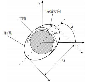
2.2 一次谐振运动的特点如图 2所示,轴系一次谐振运动相当于主轴以角速率ω0转动的同时又在一定的小角度范围内进行摆动,设摆动角范围为2A,如果摆动方向与x轴正向夹角为λ,则在自准直仪两个方向的读数为:
|
图 2 轴系的转动方向与一次谐振运动方向 Figure 2 The direction of rotation of the shaft and the direction of the first harmonic resonance of the shaft |
| $ x\left( t \right) = A\cos \lambda \sin \left( {{\omega _0}t + \alpha } \right), $ |
| $ y\left( t \right) = A\sin \lambda \sin \left( {{\omega _0}t + \alpha } \right), $ |
式中x(t)、y(t)是完全相关且相位一致,幅值是由摆幅范围A和谐振方位角λ共同决定的.
| $ y\left( t \right) = x\left( t \right)\tan \lambda . $ | (9) |
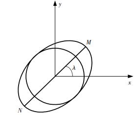
式(10)、(11)中一次谐波的Lissajous图如图 3所示,其中线段MN表示轴系的一次谐振运动,圆周表示轴系上平面反射镜的安装误差.而椭圆就是上述两者的合成,其代表了自准直仪测量回转轴系的实际数据轨迹.下面内容阐述的是将自准直仪二维测量数据中的一次谐波分离成两个部分,分别为正交的和同相的一次谐波.
|
图 3 轴系一次谐振运动的分解 Figure 3 The decomposition of the first harmonic resonance motion of the shaft |
椭圆的参数方程为:
| $ {g_x}\left( {{\gamma _i}} \right) = \Delta {\theta _{xlc}}cos{\gamma _i} + \Delta {\theta _{xls}}\sin {\gamma _i}, $ | (10) |
| $ {g_y}\left( {{\gamma _i}} \right) = \Delta {\theta _{ylc}}cos{\gamma _i} + \Delta {\theta _{yls}}\sin {\gamma _i}. $ | (11) |
椭圆上的点到平均回转轴线距离的平方为:
| $ s = g_x^2\left( \gamma \right) + g_y^2\left( \gamma \right), $ |
| $ s = \frac{1}{2}\left( {\Delta \theta _{xlc}^2 + \Delta \theta _{xls}^2 + \Delta \theta _{ylc}^2 + \Delta \theta _{yls}^2} \right) + \sqrt {\frac{1}{4}{{\left( {\Delta \theta _{xlc}^2 + \Delta \theta _{ylc}^2 - \Delta \theta _{xls}^2 - \Delta \theta _{yls}^2} \right)}^2} +\\ {{\left( {\Delta {\theta _{xlc}}\Delta {\theta _{xls}} + \Delta {\theta _{ylc}}\Delta {\theta _{yls}}} \right)}^2}} \sin \left( {2\gamma + \beta } \right), $ |
其中tan β的表达式为
| $ tan\beta = \frac{{\Delta \theta _{xlc}^2 + \Delta \theta _{ylc}^2 - \Delta \theta _{xls}^2 - \Delta \theta _{yls}^2}}{{2\left( {\Delta {\theta _{xlc}}\Delta {\theta _{xls}} + \Delta {\theta _{ylc}}\Delta {\theta _{yls}}} \right)}}. $ |
从图 3可知,点M、N到椭圆中心的距离最大,令
| $ \lambda = arctan\frac{{{g_y}\left( {\frac{{\rm{ \mathsf{ π} }}}{4} - \frac{\beta }{2}} \right)}}{{{g_x}\left( {\frac{{\rm{ \mathsf{ π} }}}{4} - \frac{\beta }{2}} \right)}}. $ |
轴系一次谐振运动的参数方程表示为:
| $ {l_x}\left( {{\gamma _i}} \right) = \left( {{e_x}\cos {\gamma _i} + {e_y}\sin {\gamma _i}} \right)\cos \lambda , $ |
| $ {l_y}\left( {{\gamma _i}} \right) = \left( {{e_x}\cos {\gamma _i} + {e_y}\sin {\gamma _i}} \right)\sin \lambda . $ |
上述阐述可知,平面反射镜的安装误差所造成的圆周运动为:
| $ \begin{array}{l} {h_x}\left( {{\gamma _i}} \right) = \Delta {\theta _{xlc}}cos{\gamma _i} + \Delta {\theta _{xls}}\sin {\gamma _i} - \\ \;\;\;\;\;\;\;\;\;\;\;\;\;\left( {{e_x}\cos {\gamma _i} + {e_y}\sin {\gamma _i}} \right)\cos \lambda , \end{array} $ | (12) |
| $ \begin{array}{l} {h_y}\left( {{\gamma _i}} \right) = \Delta {\theta _{ylc}}cos{\gamma _i} + \Delta {\theta _{yls}}\sin {\gamma _i} - \\ \;\;\;\;\;\;\;\;\;\;\;\;\;\left( {{e_x}\cos {\gamma _i} + {e_y}\sin {\gamma _i}} \right)\sin \lambda . \end{array} $ | (13) |
由于hx(γi)、hy(γi)是相位正交的一次谐波,参照式(1)、(2)和式(12)、(13)可得:
| $ \Delta {\theta _{xlc}} - {e_x}\cos \lambda = \Delta {\theta _{yls}} - {e_y}\sin \lambda = \Delta {\beta _{y2}}, $ | (14) |
| $ \Delta {\theta _{xls}} - {e_y}\cos \lambda = - \left( {\Delta {\theta _{ylc}} - {e_x}\sin \lambda } \right) = \Delta {\beta _{x2}}. $ | (15) |
根据式(14)、(15),求解关于ex、ey的方程组,可得到:
| $ {e_x} = \left( {\Delta {\theta _{xls}} + \Delta {\theta _{ylc}}} \right)\sin \lambda + \left( {\Delta {\theta _{xlc}} - \Delta {\theta _{yls}}} \right)\cos \lambda , $ |
| $ {e_y} = \left( { - \Delta {\theta _{xlc}} + \Delta {\theta _{yls}}} \right)\sin \lambda + \left( {\Delta {\theta _{xls}} + \Delta {\theta _{ylc}}} \right)\cos \lambda , $ |
至此,一次谐振的参数ex、ey以及谐振方位角λ均已得出.
3 改进的倾角回转误差模型及其数据处理由式(14)、(15)以及式(1)、(2)可得:
| $ \begin{array}{l} \Delta {\beta _{y2}} = \left( {1 - {{\cos }^2}\lambda } \right)\Delta {\theta _{xlc}} + \Delta {\theta _{yls}}{\cos ^2}\lambda - \\ \;\;\;\;\;\;\;\;\;\;\;\left( {\Delta {\theta _{ylc}} + \Delta {\theta _{xls}}} \right)\sin \lambda \cos \lambda , \end{array} $ |
| $ \begin{array}{l} \Delta {\beta _{x2}} = \left( {1 - {{\cos }^2}\lambda } \right)\Delta {\theta _{xls}} + \Delta {\theta _{ylc}}{\cos ^2}\lambda - \\ \;\;\;\;\;\;\;\;\;\;\;\left( { - \Delta {\theta _{xlc}} + \Delta {\theta _{yls}}} \right)\sin \lambda \cos \lambda , \end{array} $ |
扣除平面反射镜的安装误差Δβx2、Δβy2与自准直仪的对准误差fx、fy后可得:
| $ {\varepsilon _x}\left( {{\gamma _i}} \right) = {f_x}\left( {{\gamma _i}} \right) - \overline {{f_x}} - \Delta {\beta _{y2}}\cos {\gamma _i} - \Delta {\beta _{x2}}\sin {\gamma _i}, $ | (16) |
| $ {\varepsilon _y}\left( {{\gamma _i}} \right) = {f_y}\left( {{\gamma _i}} \right) - \overline {{f_y}} - \Delta {\beta _{y2}}\sin {\gamma _i} - \Delta {\beta _{x2}}\cos {\gamma _i}. $ | (17) |
由式(16)、(17)可知,改进后的倾角回转误差的数据处理算法只扣除了Δβx2、Δβy2安装误差产生的一次谐波,保留了轴系固有的一次谐振运动误差,这种评估方法更为客观、合理和精确.
则合成后的倾角回转误差为
| $ {\varepsilon _{xy}}\left( {{\gamma _i}} \right) = \sqrt {\varepsilon _x^2\left( {{\gamma _i}} \right) + \varepsilon _y^2\left( {{\gamma _i}} \right)} , $ | (18) |
取εxy(γi)的最大值作为轴系的倾角回转误差.
4 改进后的回转误差模型的误差分析数据通过对比同一回转轴系在不同安装误差下所计算出的倾角回转误差数据验证该方法的正确性,见表 1.
| 表 1 不同平面反射镜安装误差下的倾角回转误差数据 Table 1 The wobble data under different installation errors of the reflected mirror |
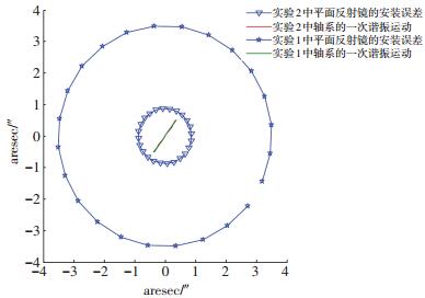
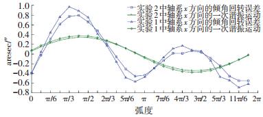
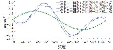
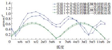
从表 1中可以看到,采用改进后的数据处理算法即式(18)得到实验1中轴系的倾角回转误差为±1.06″, 其一次谐振运动的摆幅为-0.64″~+0.64″, 实验2中轴系倾角回转误差为± 0.91″,其一次谐振运动的摆幅为-0.60″~+0.60″,两次实验的一次谐振运动的摆幅基本一致;而按照传统的数据处理算法即式(8)得到实验1的倾角回转误差为±0.67″,实验2的倾角回转误差为±0.58″,所以按照传统的数据处理方法,得到的倾角回转误差偏小,因为它把轴系本身的一次谐振运动误差扣除掉了.从图 4也可以看出两次实验一次谐振运动的方位角基本相同,其中实验1的一次谐振直线斜率为1.36,而实验2的一次谐振直线斜率为1.42,以上这些都足以说明两次实验中轴系的一次谐振运动有着很高的重复度.从图 4~7中也可以看出轴系的倾角回转误差和一次谐振运动的重复度很高,两次实验测试的轴系倾角回转误差仅差0.15″,从而验证了本文所给出算法的正确性,同时也说明了对于回转精度高的轴系,其一次谐振运动是不能被忽略的,从表 1数据可以看出实验1中一次谐振运动所占整体轴系倾角回转误差为60.4%,而实验2中一次谐振运动所占整体轴系倾角回转误差为65.9%,此轴系的一次谐振运动误差占倾角回转误差比例较大,其在工艺上仍有改进的空间.
|
图 4 实验1和实验2中平面镜安装偏差和一次谐振运动的Lissajous图 Figure 4 The Lissajous figures of the installation error of the reflected mirror and the first harmonic resonance motion in Experiment 1 and Experiment 2 |
|
图 5 实验1和实验2中轴系x方向倾角回转误差和一次谐振运动的对比曲线 Figure 5 The contrast curves of the angular rotation errors of x-direction and the first harmonic resonance motion in Experiment 1 and Experiment 2 |
|
图 6 实验1和实验2中轴系y方向倾角回转误差和一次谐振运动的对比曲线 Figure 6 The contrast curves of the angular rotation errors of y-direction and the first harmonic resonance in Experiment 1 and Experiment 2 |
|
图 7 实验1和实验2中合成后的轴系倾角回转误差和一次谐振运动的对比曲线 Figure 7 The contrast curves of the angular rotation errors of synthesis and the first harmonic resonance motion in Experiment 1 and Experiment 2 |
1) 将自准直仪测试数据中的一次谐波分解为同相和正交的一次谐波两部分,并在数据处理过程中扣除了安装误差引起的正交一次谐波,保留了同相的一次谐振项,使轴系倾角回转误差的数据处理方法更加合理和精确.
2) 通过改变平面反射镜的安装误差,对同一轴系的倾角回转误差进行两次对比测试,从两组实验数据中分离出的轴系一次谐振运动具有一致性,从而验证了本文所给出算法的正确性.本文的方法同样适用于径向回转误差中一次谐振的分离与测试.
| [1] |
任顺清, 王俊柱. 用水平仪测试倾角回转误差的数据处理[J].
哈尔滨工业大学学报, 2006, 38(6): 837-839.
REN Shunqing, WANG Junzhu. Data processing method of calculating wobble error with level instrument[J]. Journal of Harbin Institute of Technology, 2006, 38(6): 837-839. |
| [2] |
谭文锋, 胡春生, 王省书, 等. 基于电子水平仪的转轴倾角回转误差测量方法[J].
光学与光电技术, 2014, 12(3): 39-43.
TAN Wenfeng, HU Chunsheng, WANG Xingshu, et al. Wobble error measuring methods of rotary shaft based on electronic gradienter[J]. Optics & Optoelectronic Technology, 2014, 12(3): 39-43. |
| [3] |
任顺清, 房振勇, 吴广玉, 等. 竖直轴系倾角回转误差的两种测试方法的比较[J].
中国惯性技术学报, 2000, 8(3): 74-78.
REN Shunqing, FANG Zhenyong, WU Guangyu, et al. The contrast of two methods of mea-suring wobble error in perpendicular axis system[J]. Journal of Chinese Inertial Technology, 2000, 8(3): 74-78. DOI: 10.13695/j.cnki.12-1222/o3.2000.03.017 |
| [4] |
罗海燕, 翟超, 金熠. 回转误差测量新方法的研究[C]. 厦门: 全国测控计量仪器仪表学术年会. 2007.
LUO Haiyan, ZHAI Chao, JIN Yi. Study on a new method for spindle radial error measurement[C].Xiamen: 2007 National Conference on Measurement and Control, Measurement and Instrumentation, 2007. |
| [5] |
熊万里, 侯志泉, 吕浪. 液体静压主轴回转误差的形成机理研究[J].
机械工程学报, 2014, 50(7): 112-119.
XIONG Wanli, HOU Zhiquan, LV Lang. Study on the mechanism of hydrostatic spindle rotational error motion[J]. Journal of Mechanical Engineering, 2014, 50(7): 112-119. DOI: 10.3901/JME.2014.07.112 |
| [6] |
苏燕芹, 张景旭, 陈宝刚, 等. 谐波分析方法在提高精密转台回转精度中的应用[J].
红外与激光工程, 2014, 43(1): 274-278.
SU Yanqin, ZHANG Jingxu, CHEN Baogang, et al. Harmonic analysis application in accuracy improvement of precise turntable[J]. Infrared and Laser Engineering, 2014, 43(1): 274-278. DOI: 10.3969/j.issn.1007-2276.2014.01.048 |
| [7] |
芮晓健, 颜景平. 主轴回转精度测试中的误差分离技术[J].
南京理工大学学报, 1988(3): 78-84.
RUI Xiaojian, YAN Jingping. The error separation technique in the measurement of spindle rotation precision[J]. Journal of Nanjing University of Science and Technology, 1988(3): 78-84. DOI: 10.14177/j.cnki.32-1397n.1988.03.012 |
| [8] |
江志伟. 机床主轴回转精度测试中的一次分量及其处理[J].
机床, 1985(1): 38-40.
JIANG Zhiwei. Treatment of first component in the test of spindle rotating accuracy[J]. Machine Tool, 1985(1): 38-40. |
| [9] |
杜正春, 杨建国, 姚振强, 等. 主轴回转误差补偿机理和动力学模型研究[J].
机械工程学报, 2003, 39(3): 48-52.
DU Zhengchun, YANG Jianguo, YAO Zhenqiang, et al. Research on mechanism and dynamic model of spindle rotation induced error compensation[J]. Journal of Mechanical Engineering, 2003, 39(3): 48-52. |
| [10] |
CAPPA S, REYNAERTS D, AL-BENDER F. A sub-nanometre spindle error motion separation technique[J].
Precision Engineering, 2014, 38(3): 458-471.
DOI: 10.1016/j.precisioneng.2013.12.011 |
| [11] |
ZHU Jibin, ZHANG Jinhua, GUO Junkang. Research of the influence of geometrical factors on rotary accuracy of high-precision spindle[C]//Proceedings of the IEEE International Symposium on Assembly and Manufacturing. Xi'an, China: IEEE, 2013:264-269.
|
| [12] |
JIN Lan, YAN Zhaoyang, XIE Liming, et al. An experimental investigation of spindle rotary error on high-speed machining center[J].
International Journal of Advanced Manufacturing Technology, 2014, 70(1/2/3/4): 327-334.
DOI: 10.1007/s00170-013-5270-9 |
| [13] |
MA Ping, ZHAO Chunming, LU Xinhui, et al. Rotation error measurement technology and experimentation research of high-precision hydrostatic spindle[J].
International Journal of Advanced Manufacturing Teconology, 2014, 73(9/10/11/12): 1313-1320.
DOI: 10.1007/s00170-014-5905-5 |
| [14] |
孙郅佶, 安晨辉, 杨旭, 等. 超精密机床主轴回转误差在线测试与评价技术[J].
制造技术与机床, 2015(9): 118-123.
SUN Zhiji, AN Chenhui, YANG Xu, et al. On-line measurement and evaluation of spindle error motion in ultra precision machine tool[J]. Manufacturing Technology & Machine Tool, 2015(9): 118-123. DOI: 10.3969/j.issn.1005-2402.2015.09.034 |
| [15] |
朱永生, 岳鹏飞, 闫柯, 等. 精密主轴动态回转误差的实验研究[J].
机床与液压, 2015, 43(7): 18-21.
ZHU Yongsheng, YUE Pengfei, YAN Ke, et al. Experimental study on the dynamic error motion of the precise spindle system[J]. Machine Tool & Hydraulics, 2015, 43(7): 18-21. DOI: 10.3969/j.issn.1001-3881.2015.07.005 |
| [16] |
李树森, 任毅, 陈素平, 等. 静压气体轴承主轴系统回转误差的控制与补偿[J].
润滑与密封, 2016, 41(2): 23-25.
LI Shusen, REN Yi, CHEN Suping, et al. Control and compensation of rotary error by aerostatic bearing spindle system[J]. Lubrication Engineering, 2016, 41(2): 23-25. DOI: 10.3969/j.issn.0254-0150.2016.02.005 |
| [17] |
颜景平. 主轴回转误差测量及其消偏问题[J].
南京工学院学报, 1984(2): 1-8.
YAN Jingping. Discussions on measurement of spindle error motion[J]. Journal of Nanjing Institute of Technology, 1984(2): 1-8. |
 2017, Vol. 49


