移动机器人可携带多种载荷进入危险或未知的环境执行任务,适用于生产、国防和科学研究等多个领域,已经在空间探测、灾害救援、防暴反恐、消防救险等任务中发挥重要作用[1-2].根据运动形态,地面移动机器人可分为轮式、履带式、腿式、轮腿复合、轮履复合等多种结构形式.轮式机器人具有结构简单、效率高、质量轻和易于控制等优点,适应于平坦、不易沉陷的地形环境,新型轮系和悬架使轮式机器人在空间探测和高速平台等方面得到广泛应用.履带式移动机构结构紧凑、越野能力强,目前应用于机器人的移动结构主要包括两平行履带结构[3]、鳍状肢履带结构[4]、四履带结构[5-7]和六履带结构[8]等.
相对于传统的地面移动机器人,可重构机器人能根据工作环境的变化改变自身构型,从而具有更强的适应能力.针对两平行履带结构越障能力弱的特点,Yamauchi[9]研制了采用鳍状肢履带结构的Packbot系列机器人,黑沫[10]提出了基于平行四边形机构的可变形履带机器人,李智卿等[11-12]研制了通过改变履带轮和运动轮位置实现轮-履多姿态转换的NEZA-Ⅰ机器人. Paillat等[13]研制的B2P2机器人,实现了轮轴之间角度和距离的变化,距离调节由长螺杆机构完成.吴兴[14]研制的变体轮通过液压传动机构直连伸展臂来控制伸展臂的展开和收回.以色列埃尔比特系统公司推出了一款具有轮履复合功能的可重构履带机器人(VIPeR)[15],其履带变形机构可将整根履带收缩于轮体内,从而使机器人具有轮式和履带式两种运动形态,但不具备翻转运动形态.李海泓等[16-17]研制的轮履变结构反恐机器人,转动传动轴带动曲柄支撑摆杆,实现形态转换,体积小、便于携带.
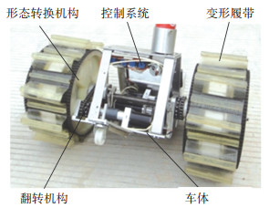
本文进行了不同于上述机器人的一种可重构轮履复合式移动机器人新型结构设计,模式转换通过并行四连杆机构实现,并进行了仿真优化,变形结构可靠性高,变形轨迹优良.样机见图 1,其具有轮式、履带式和翻转3种运动形态,实现了优越的沙地行进、原地转向、攀爬越障、翻倒后行进等多种功能.
|
图 1 机器人结构 Figure 1 Mechanical structure of the robot |
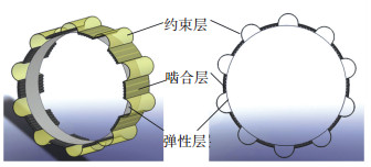
机器人的机械结构如图 1,由变形履带、形态转换机构、翻转机构、车体和控制系统构成.变形履带的结构见图 2.履带采用3层结构,由弹性层、啮合层和约束层构成.内层为弹性层,采用弹性材料,主要作用是提供预紧力并适应履带长度的变化;中间层为啮合层,离散分布的履带条与履带轮啮合,传递运动与动力;外层为约束层,保证变形履带完全展开的总长恒定,不受弹性层的影响.
|
图 2 变形履带 Figure 2 The structure of deformable track |
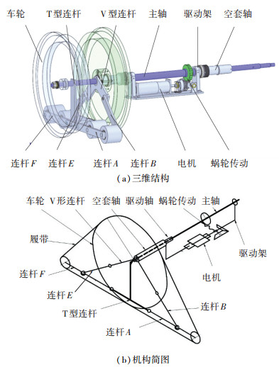
机器人运动模式的重构由形态转换机构实现,形态转换机构的结构和原理如图 3所示,其中,电机、蜗轮蜗杆、主轴、驱动架和空套轴构成驱动系统,为轮履变换过程提供驱动力. V型连杆、T型连杆和连杆A、B、E、F共同构成两套并联的四连杆机构,用于与变形履带配合实现轮式和三角履带两种行进模式的变换.机器人形态转换机构的T型连杆、蜗轮与主轴固联,V型连杆、驱动架和空套轴三者固联并可相对主轴旋转.
|
图 3 新型转换系统的结构 Figure 3 Structure of a novel transformation system |
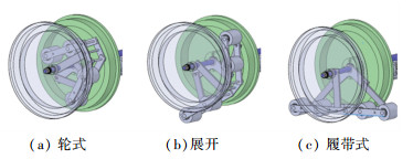
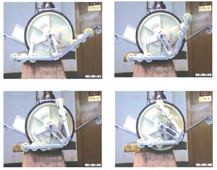
轮-履转换过程如图 4所示,形态转换机构内置于车轮内部时,如图 4(a),机器人处于轮式行进模式,在变形层弹性力作用下,履带条与履带轮完全啮合,保证啮合随带轮转动.
|
图 4 可重构结构转换过程 Figure 4 Transformation process of reconfigurable frame |
机器人需重构为履带模式时,电机驱动蜗杆相对蜗轮作空间运动,带动驱动架和V型连杆相对主轴轴线旋转,V型连杆驱动并联的两套四连杆机构展开,如图 4(b),同时,在形态转换机构的作用下,变形履带弹性层拉伸变长.当V型连杆运动到如图 4(c)所示极限位置时,形态转换机构完全展开,整个履带完全展开呈三角形,约束层被完全拉伸,并承受带轮的驱动力,限制履带的变形,履带条与履带轮分组啮合传递运动,从而实现了机器人的轮履转换.
1.2 机器人运动形态机器人通过调整自身机构能实现轮式(图 5(a))、履带式(图 5(b))和翻转(图 5(c))3种运动形态.机器人处于翻转形态时,在稳定架提供的反力矩作用下,三角履带轮整体绕主轴翻转.

|
图 5 机器人运动形态及其越障原理 Figure 5 The locomotion modes and the obstacle overcomingprinciple |
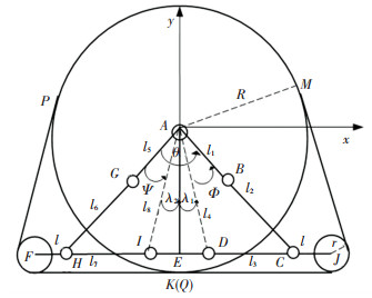
对应图 3所示的轮履形态转换机构设计模型,取T型连杆为机架构件(固定件),以履带轮圆心为参考点,在图 6所示的直角坐标系的基础上,建立形态转换机构的参数化几何模型,图 6中:
|
图 6 可重构结构示意 Figure 6 Schematic diagram of the reconfigurable frame |
1) 履带轮圆心为A,其半径为R;履带支撑轮的圆心分别为F和J,半径为r;
2) 四连机构ABCD的长度AB=l1,BC=l2,DC=l3,AD=l4;四连杆机构AGHI的长度AG=l5,GH=l6,HI=l7,AI=l8;连杆HF=CJ=l;
3) θ为AB与AG之间的夹角,λ1(λ2)为AE与AD(AI)的夹角,二者为常值.
在两套联动的四杆机构中,连杆AD和连杆AI与机架AE固联,分别为四连杆ABCD和AGHI的固定杆.形态转换时,连杆AB为主动杆,定义连杆AB相对AD的夹角Φ为驱动角,规定逆时针方向为正.注意到四连杆ABCD和AGHI是联动的,连杆AG与连杆AB的夹角θ固定,则AG为主动杆,定义Ψ为连杆AG相对AI的夹角,逆时针方向为正.可见,Ψ、Φ、θ、λ存在如下几何关系:
| $ \left( {\mathit{\Psi }\;{\lambda _1}\;{\lambda _2}} \right) = \left( {{\lambda _1} + {\lambda _2} + \mathit{\Phi } - \theta \arccos \frac{{R - r}}{{{l_4}}}\arccos \frac{{R - r}}{{{l_8}}}} \right). $ |
显然,对于特定的机器人,θ、λ为常值,当Φ确定时,可计算得到Ψ.
机器人形态转换过程中,变形履带的长度变化主要取决于履带支撑轮J和F相对于履带轮的位置,下面研究履带支撑轮J和F的运动学模型.
取右半侧的支撑轮J为研究对象,在平面坐标系中,J的平面坐标可以表示为矢量
| $ \mathit{\boldsymbol{AJ}} = \mathit{\boldsymbol{AD}} + \left( {{l_3} + l} \right)/{l_3}\mathit{\boldsymbol{DC}}. $ |
令AB、BC、DC、AD方向角分别为θ1、θ2、θ3、θ4,则有:
| $ \left\{ {\begin{array}{*{20}{c}} {{l_1}\cos {\theta _1} + {l_2}\cos {\theta _2} = {l_3}\cos {\theta _3} + {l_4}\cos {\theta _4},}\\ {{l_1}\sin {\theta _1} + {l_2}\sin {\theta _2} = {l_3}\sin {\theta _3} + {l_4}\sin {\theta _4}.} \end{array}} \right. $ | (1) |
式中:θ1=-π/2+λ1+Φ,θ4=-π/2+λ1.
对式(1)移项平方消去θ2,整理得
| $ \left( {D - C} \right){\beta ^2} + 2S\beta + C + D = 0. $ | (2) |
式中:C=2l3(l1cos θ1-l4cos θ4),β=tan(θ3/2),S=2 l3(l1sin θ1-l4sin θ4),D=l22-l32-l42-l12+2l1l4(cos θ1cos θ4+sin θ1sin θ4).
解式(2),得
| $ {\theta _3} = 2{\tan ^{ - 1}}\frac{{ - S \pm \sqrt { - {S^2} - {D^2} + {C^2}} }}{{D - C}},{\theta _3} \in \left[ {0,{\rm{ \mathsf{ π} }}/2} \right]. $ |
从而支撑轮J的运动轨迹为
| $ \begin{array}{l} \mathit{\boldsymbol{AJ}} = \left( {{l_4}\cos {\theta _4} + \left( {{l_3} + l} \right)\cos {\theta _3}} \right) + {\rm{i}}\left( {{l_4}\sin {\theta _4} + } \right.\\ \;\;\;\;\;\;\;\;\left. {\left( {{l_3} + l} \right)\sin {\theta _3}} \right). \end{array} $ | (3) |
同理,可得到F的运动轨迹为
| $ \begin{array}{l} \mathit{\boldsymbol{AF}} = \left( {{l_8}\cos {\theta _8} + \left( {{l_7} + l} \right)\cos {\theta _7}} \right) + {\rm{i}}\left( {{l_8}\sin {\theta _8} + } \right.\\ \;\;\;\;\;\;\;\;\left. {\left( {{l_7} + l} \right)\sin {\theta _7}} \right). \end{array} $ | (4) |
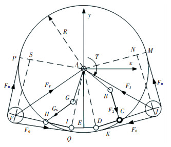
机器人运动模式由轮式向履带式转换时,在驱动力矩T的作用下,形态转换机构的V形架BAG顺时针方向旋转,推动变形机构向外伸展,支撑轮J和F对变形履带施加作用力,同时变形履带对支撑轮J和支撑轮F有反作用力F0,受力如图 7所示.
|
图 7 可重构结构的受力分析 Figure 7 Stress analysis of reconfigurable mechanism |
以其一支撑轮i(i为F或J)为例,支撑轮两侧受到的履带作用力大小相等,均为F0,则支撑轮受到的合力Fi大小为
| $ \left| {{\mathit{\boldsymbol{F}}_i}} \right| = \left\{ \begin{array}{l} 2{F_0}\frac{{\sqrt {R_i^2 - {{\left( {R - r} \right)}^2}} }}{{{R_i}}},{R_i} \ge R - r;\\ 0,\;\;\;\;\;\;\;\;\;\;\;\;\;\;\;\;\;\;\;\;\;\;\;\;\;\;{R_i} < R - r. \end{array} \right. $ | (5) |
式中:F0=k(l-l0), l为履带实际长度,l0=2πR为履带展开前长度,k为履带弹性系数.
以V形支架AGB为对象,则驱动力矩T为
| $ \mathit{\boldsymbol{T}} - {\mathit{\boldsymbol{F}}_6} \times \mathit{\boldsymbol{AG}} - {\mathit{\boldsymbol{F}}_2} \times \mathit{\boldsymbol{AB}} = 0. $ |
式中:F6为连杆FI受到连杆GH的力,有F6×IH+FF×IF=0;F2为连杆DJ受到连杆BC的力,有F2×DC+FJ×DJ =0.
整理得
| $ \begin{array}{l} \left| \mathit{\boldsymbol{T}} \right| = \left| {\frac{{{\mathit{\boldsymbol{F}}_J} \times \mathit{\boldsymbol{DJ}}}}{{{l_3}\sin \left( {{\theta _3} - {\theta _2}} \right)}}\left( {\cos {\theta _2} + {\rm{i}}\sin {\theta _2}} \right) \times \mathit{\boldsymbol{AB}}} \right| + \\ \;\;\;\;\;\;\;\left| {\frac{{{\mathit{\boldsymbol{F}}_F} \times \mathit{\boldsymbol{IF}}}}{{{l_7}\sin \left( {{\theta _7} - {\theta _6}} \right)}}\left( {\cos {\theta _6} + {\rm{i}}\sin {\theta _6}} \right) \times \mathit{\boldsymbol{AG}}} \right|. \end{array} $ | (6) |
选取R=150 mm,k=1 N/mm的机器人为研究对象, 取R/r=6,机器人的初始驱动角Φ=θ/2-λ1, 初选得到一组机器人设计参数,如表 1所示.
| 表 1 机器人设计参数 Table 1 Design parameters of the robot |
履带式机器人形态转换机构完全展开, 其几何构型必须满足如下几何约束:
| $ \left\{ \begin{array}{l} R - r = \left( {{l_1} + {l_2}} \right)\cos \frac{\theta }{2} = \left( {{l_5} + {l_6}} \right)\cos \frac{\theta }{2},\\ R - r = {l_4}\cos {\lambda _1} = {l_8}\cos {\lambda _2},\\ {l_3} = \left( {R - r} \right)\left( {\tan \frac{\theta }{2} - \tan {\lambda _1}} \right),\\ {l_7} = \left( {R - r} \right)\left( {\tan \frac{\theta }{2} - \tan {\lambda _2}} \right). \end{array} \right. $ | (7) |
形态转换机构处于收缩状态的几何条件为
| $ \left\{ \begin{array}{l} \left| {\mathit{\boldsymbol{AJ}}} \right| \le R - r,\\ \left| {\mathit{\boldsymbol{AF}}} \right| \le R - r,\\ {\theta _6} = {\rm{ \mathsf{ π} }} + \arctan \frac{{{l_7}\sin {\theta _7} + {l_8}\sin {\theta _8} - {l_5}\sin {\theta _5}}}{{{l_7}\cos {\theta _7} + {l_8}\cos {\theta _8} - {l_5}\cos {\theta _5}}} \ge \\ \;\;\;\;\;\;\frac{{\rm{ \mathsf{ π} }}}{2} + \mathit{\Phi } + {\lambda _1} - \theta . \end{array} \right. $ | (8) |
根据轨迹方程(3)和(4),以式(7)表示的完全展开状态为机器人初始构型,以式(8)表示的完全收缩状态为最终构型,以驱动角Φ为运动参数,得到机器人的运动轨迹如图 8所示,仿真表明机构能够实现轮-履转换.

|
图 8 支撑轮J与F的运动轨迹 Figure 8 Motion trajectory of the support wheel J and F |
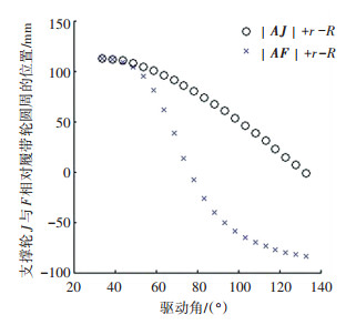
由图 9可进一步看出,当驱动角Φ=77.56 °时,支撑轮F相对履带轮的距离(|AF|+r-R)率先到0,表明支撑轮F已经收缩到履带轮内部并相切;当驱动角Φ=134.98 °时,支撑轮J相对履带轮的距离(|AJ`|+r-R)接近于0,表明支撑轮J已经收缩到履带轮内部并相切, 而此时支撑轮F相对履带轮的距离为负值,表明支撑轮F完全收缩到履带内部,至此机器人机构已经完成由履带式形态向轮式形态的转换.
|
图 9 支撑轮J与F相对履带轮的位置 Figure 9 Location of the support wheel J and F relative to the track wheel |
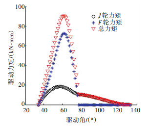
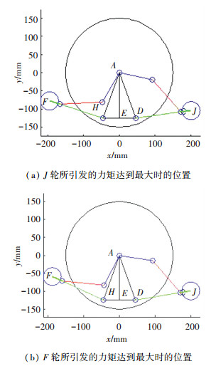
根据轨迹方程(3)和(4),结合支撑轮的受力计算公式(5)和驱动力矩计算公式(6),可以得到形态转换机构的驱动力矩与驱动角Φ的关系, 见图 10.可以看出,当机器人处于完全展开状态时(Φ=34 °),支撑轮J和F所引发的驱动力矩均为0,处于该状态时驱动电机无需施加力矩,便于越障.当驱动角Φ=57.76°时,支撑轮J的驱动力矩达到峰值,为1.84×10⁴ N·mm,机器人构型见图 11(a).当驱动角Φ=61.72 °时,支撑轮F所引发的驱动力矩达到峰值,为7.27×10⁴N·mm,机器人构型如图 11(b),机器人总驱动力矩也达到最大值9.05×10⁴ N·mm.
|
图 10 驱动力矩随驱动角变化曲线 Figure 10 Diving torque solution in the course of input angle change |
|
图 11 支撑轮引发的力矩达到最大时位置 Figure 11 Configuration of the wheel J and F with the maximum torque |
由图 8可知,轮J和轮F收缩过程中存在不同步、完全收缩状态下不对称现象;由图 10可知,轮F引起的驱动力矩在Φ=57.76 °时出现尖峰,对电机的驱动力矩要求较高.针对上述现象,以式(6)表示的驱动力矩最小化为目标函数,表示为
| $ \min T\left( {\theta ,{\lambda _1},{\lambda _2},{l_1},{l_5},l} \right). $ |
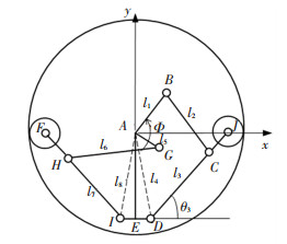
以最终同步收缩为约束条件,如图 12所示.考虑到支撑轮F先于支撑轮J收缩于履带轮内,因此当|AF|=R-r时,有Re(AF)=-Re(AJ),Im(AF)=Im(AJ).
|
图 12 收缩过程的最终位置 Figure 12 The final position of the contraction process |
采用Matlab对机器人结构进行参数化研究,得到优化后的设计参数如表 2所示.
| 表 2 优化后的机器人设计参数 Table 2 The optimized design parameters of the robot |
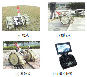
根据表 2的设计参数和负载要求,选择Maxon的RE35系列电机,采用遥控器+松乐SLA-12VDC-SL-C继电器控制方式,研制了面向火灾灾情探测和救援的机器人.通过重构,机器人可以实现轮式(图 13(a))、翻转式(图 13(b))和履带式(图 13(c))3种运动形态.
|
图 13 样机的运动形态和遥控器 Figure 13 Locomotion modes and remote operating terminal of prototype |
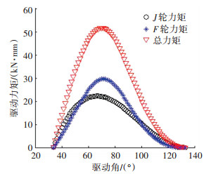
依据表 2设计参数,计算得到驱动力矩与驱动角Φ的关系如图 14所示,驱动电机所需最大力矩为10.9×10⁴ N·mm.与优化前驱动力矩相比,总力矩和F轮力矩明显降低且变得平滑,对电机要求降低.
|
图 14 驱动力矩随驱动角变化曲线 Figure 14 Diving torque solution in the course of input angle change |
|
图 15 机器人可重构机构 Figure 15 Reconfigurable mechanisms of the robot |
机器人沙地行进动作过程如图 16所示.

|
图 16 机器人沙地行进 Figure 16 Robot moving on sands |
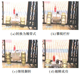
图 17为机器人攀越垂直高度为140 mm栏杆时的动作过程.当机器人遇到轮式状态不可翻越的栏杆时(图 17(a)),机器重构为三角履带状态,并通过三角履带的整体翻转攀爬到栏杆(图 17(b)),在翻转力矩的持续作用下,三角履带继续翻转(图 17(c)),直至机器人整体翻越障碍(图 17(d)).机器人实际越障能力除几何因素外,还受到机器人越障姿态调整、摩擦、驱动力矩等因素的影响.
|
图 17 机器人攀爬垂直障碍 Figure 17 Robot crossing vertical obstacle |
1) 提出并研制了一种适应多种地貌可越障的轮-履复合移动机器人平台,集成两轮机器人、三角履带机器人、翻转3种运动形态于一体,履带的几何形状以及机器人运动形式可根据地形的变化作出调整.
2) 在对并联四连杆机构进行运动学和力学分析仿真的基础上,对更优的结构参数进行了探索,实现了支撑轮转换轨迹对称性目标以及降低了对驱动力矩的要求.
3) 该轮-履复合机器人能通过自身机构的及时调整, 以灵活多变的运动形式和姿态通过地面特征不断变化的路面环境.同时该平台通过翻转形态可克服其他机器人无法克服的障碍,具有良好的越障性能.
| [1] |
高峻峣. 国外军用地面机器人系统综述[J]. 机器人, 2003, 25(z1): 746-755. GAO Junyao. Survey of military mobile robotic systems in foreign country[J]. Robot, 2003, 25(z1): 746-755. DOI:10.3321/j.issn:1002-0446.2003.z1.038 |
| [2] |
闫清东, 魏丕勇, 马越. 小型无人地面武器机动平台发展现状和趋势[J]. 机器人, 2004, 26(4): 373-379. YAN Qingdong, WEI Piyong, MA Yue. Status and trends of small unmanned ground weapon mobile platforms[J]. Robot, 2004, 26(4): 373-379. DOI:10.3321/j.issn:1002-0446.2004.04.017 |
| [3] |
WELLS P, DEGUIRE D. TALON: a universal unmanned ground vehicle platform, enabling the mission to be the focus[C]// Proceedings of SPIE-The International Society for Optical Engineering. Orlando: SPIE, 2005: 5804. DOI: 10.1117/12.602887.
|
| [4] |
LEE M H, DAS J, SORDELET D J, et al. Applications for the MATILDA robotic platform[J]. Proceedings of SPIE-The International Society for Optical Engineering, 2002, 4715(12): 206-213. DOI:10.1117/12.474451 |
| [5] |
MATTHIES L, XIONG Y, HOGG R, et al. A portable, autonomous, urban reconnaissance robot[J]. Robotics & Autonomous Systems, 2002, 40(2/3): 163-172. DOI:10.1016/S0921-8890(02)00241-5 |
| [6] |
段星光, 黄强, 李京涛, 等. 多运动模式的小型地面移动机器人设计与实现[J]. 中国机械工程, 2007, 18(1): 8-12. DUAN Xingguang, HUANG Qiang, LI Jingtao, et al. Design and implementation of a small ground mobile robot with multi-locomotion modes[J]. China Mechanical Engineering, 2007, 18(1): 8-12. DOI:10.3321/j.issn:1004-132X.2007.01.003 |
| [7] |
段星光, 黄强, 李科杰. 小型轮履腿复合式机器人设计及运动特性分析[J]. 机械工程学报, 2005, 41(8): 108-113. DUAN Xingguang, HUANG Qiang, LI Kejie. Design and motion analysis of miniature wheel-track-legged mobile robot[J]. Journal of Mechanical Engineering, 2005, 41(8): 108-113. DOI:10.3321/j.issn:0577-6686.2005.08.018 |
| [8] |
冯虎田, 欧屹, 高晓燕. 小型地面移动机器人特殊运行姿态动力学建模与分析[J]. 南京理工大学学报(自然科学版), 2006, 30(4): 486-490. FENG Hutian, OU Yi, GAO Xiaoyan. Dynamic modeling and analysis of miniature ground-moving robot based on special moving pose[J]. Journal of Nanjing University of Science and Technology, 2006, 30(4): 486-490. DOI:10.3969/j.issn.1005-9830.2006.04.021 |
| [9] |
YAMAUCHI B M. PackBot: a versatile platform for military robotics[C]//Proceedings of the Society of Photo-optical Instrumentation Engineers. Orlando: International Society for Optical Engineering, 2004: 228-237. DOI: 10.1117/12.538328.
|
| [10] |
黑沫. 可变形履带机器人设计与运动分析[D]. 长沙: 国防科学技术大学, 2010. HEI Mo. Design and motion analysis of a reconfigurable tracked mobile robot[D]. Changsha: National University of Defense Technology, 2010. |
| [11] |
李智卿, 马书根, 李斌, 等. 具有自适应能力轮-履复合变形移动机器人的开发[J]. 机械工程学报, 2011, 47(5): 1-10. LI Zhiqing, MA Shugen, LI Bin, et al. Development of a transformable wheel-track robot with self-adaptive ability[J]. Journal of Mechanical Engineering, 2011, 47(5): 1-10. DOI:10.3901/JME.2011.05.001 |
| [12] |
LI Zhiqing, MA Shugen, LI Bin, et al. Analysis of the constraint relation between ground and self-adaptive mobile mechanism of a transformable wheel-track robot[J]. Sci China Tech Sci, 2011, 54(3): 610-624. DOI:10.1007/s11431-010-4228-5 |
| [13] |
PAILLAT J L, LUCIDARME P, HARDOUIN L. Variable geometry tracked vehicle (VGTV) prototype: conception, capability and problems problems[C/OL]//Proceedings of the First Conference on Humans Operating Unmanned Systems. (2008-10-27)[2017-10-10]. http://conferences.telecom-bretagne.eu/humous08/papers.
|
| [14] |
吴兴. 一种轮履复合救援机器人传动系统的结构设计[D]. 天津: 天津理工大学, 2014. WU Xing. The structural design of powertrain for a wheel-tracked rescue robot[D]. Tianjin: Tianjin University of Technology, 2014. |
| [15] |
昌强. 以色列埃尔比特系统公司推出新型便携式侦察机器人[J]. 应用光学, 2007(3): 349-349. CHANG Qiang. Israeli Elbit Systems Ltd has launched a new portable reconnaissance robot[J]. Journal of Applied Optics, 2007(3): 349-349. |
| [16] |
李海泓. 轮履变结构反恐机器人设计与研究[D]. 哈尔滨: 哈尔滨工业大学, 2011. LI Haihong. Design and research of anti-terrorism robot with wheel-tracked variable structure[D]. Harbin: Harbin Institute of Technology, 2011. |
| [17] |
付宜利, 李海泓, 张福海. 轮履变结构反恐机器人设计及运动学分析[J]. 机械与电子, 2011(10): 66-69. FU Yili, LI Haihong, ZHANG Fuhai. Design and kinematic analysis of anti-terrorism robot with wheel-tracked variable wtructure[J]. Achinery & Electronics, 2011(10): 66-69. DOI:10.3969/j.issn.1001-2257.2011.10.019 |
 2018, Vol. 50


