2. 中国电力工程顾问集团 东北电力设计院有限公司,长春 130021;
3. 哈尔滨工业大学 能源科学与工程学院,哈尔滨 150001
2. Northeast Electric Power Design Institute, China Power Engineering Consulting Group, Changchun 130021, China;
3. School of Energy Science and Engineering, Harbin Institute of Technology, Harbin 150001, China
发电厂汽机房是典型的高大空间、高余热建筑,机房内部有汽轮机、发电机、凝汽器和除氧器等众多产热设备,产生大量余热聚集在机房顶部.为保障夏季室内生产环境,常设置屋顶风机将热量排除.而位于寒冷地区的汽机房,冬季采暖热负荷较大,汽机房底部需设置暖风机(或大量散热器)以满足采暖需求[1].若将通风系统与热风采暖系统有机结合,利用屋顶风机反转将机房顶部的余热送至下部工作层平台,充分利用机房内设备散热进行建筑物冬季自平衡采暖,可达到很好的节能效果.因此,提出利用机房内设备的散热量满足建筑物自身采暖需求的自平衡通风采暖方案.
工程技术人员与相关学者的研究重点在汽机房夏季通风环境,对发电厂汽机房的数值模拟研究也主要集中于汽机房夏季通风的数值模拟,而对汽机房冬季供暖的数值模拟很少.且汽机房内的冬季热环境复杂,主要表现在[2]:设备产生大量热量使热空气上升,汽机房内形成较大的垂直温度梯度; 水平方向的温度分布也表现出不均匀性,如壁面处的温度要低于中心设备附近温度; 工作区域与非工作区域对温度的需求差异较大.汽机房属于高大空间建筑,建筑通风是多种复杂流体现象耦合的结果[3],文献[4]通过实验与模拟相结合的方法表明建筑通风时气流组织的复杂性及自然通风时具有多解性,因此,不能单独考虑湍流模拟在各个情况下的优劣[5],应结合大空间建筑的实测与模拟结果选择合适的湍流模型[6-7].
火力发电厂主厂房由于其特殊的构造,相比一般的高大空间建筑,其内部具有更多的高温散热设备、复杂的热力管道等,难以建立完全符合实际情况的几何模型,因此,需对实际模型进行适当简化.目前的研究中,通常将热力管道与产热设备合并处理,并对模型的几何外形进行简化,使其易于网格划分并减少模拟时的计算量[8].但对于气流组织影响较大的建筑结构和设备外边界如过于简化,会使速度场、温度场等与实际偏差较大,从而得到错误的结论.因此,需要在计算资源允许的前提下建立更为精细的模型,使温度场、速度场更加符合实际.
以某寒冷地区(冬季室外采暖计算温度为-6.6 ℃,室外通风计算温度为-2.6 ℃)发电厂汽机房为研究对象,建立其几何模型并进行结构化网格划分,对这种利用屋顶余热的自平衡采暖系统进行数值模型,对比了两种不同风量通风方案下的采暖效果,并根据模拟结果进行优化设计,为汽机房自平衡通风采暖方式的选择提供参考.
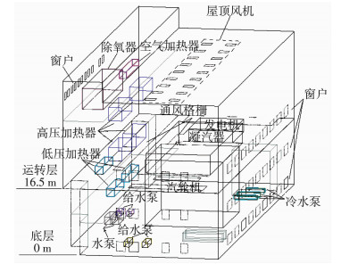
1 汽机房自平衡通风采暖模拟 1.1 工程概况该电厂为1 000 MW高效超临界燃煤机组,汽机房总长108 m,总宽度39 m,高44 m.
汽机房内设备布置情况为:底层配置有凝汽器、电动给水泵、气动给水泵前置泵、凝结水泵、开式循环冷却水泵、氢冷却器冷却水泵和主机润滑油箱等设备;中间层配置有储存油箱、低压加热器和汽水分离疏水槽等设备;运转层配置有汽轮机、发电机、励磁机、给水泵汽轮机、气动给水泵和高压加热器等设备.除氧层主要配置有除氧器和高压蒸汽加热器.其整体几何模型如图 1所示,各设备散热量如表 1、2所示.
|
图 1 汽机房几何模型 Figure 1 Geometry model of turbine house |
| 表 1 汽轮机房各设备散热量 Table 1 Heat dissipation of various equipment in turbine house |
| 表 2 除氧间各设备散热量 Table 2 Heat dissipation of various equipment in deaeration |
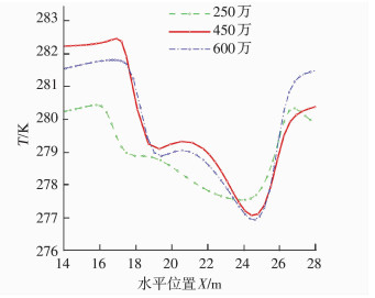
使用ANSYS平台中的ICEM软件对汽机房模型进行网格划分.网格数量对计算效率和计算精度的影响巨大,为了在保证计算精度的同时很好地控制网格数量以节约计算资源,采用结构化网格对模型进行划分.考虑到风机射流的影响,对风口与流固边界层区域进行网格加密,并采用250万、450万、600万3种网格尺寸进行网格独立性验证,结果如图 2所示.450万与600万网格尺寸的计算结果相差不大,250万的计算结果与另外两种差距较大,而600万网格的计算效率又比450万网格的效率低一倍左右,因此,本模拟选择450万的网格数作为计算网格.在后面优化的方案中,针对模拟结果中局部速度梯度较大的区域会进行相应网格加密处理.
|
图 2 网格无关性验证 Figure 2 Mesh independent verification |
利用汽机房内空气流动与传热的质量守恒方程、动量守恒方程和能量守恒方程求解空气在汽机房内温度场、速度场及压力场.汽机房内流动与传热的守恒方程[7]分别为
质量守恒方程
| $ \frac{{\partial \left( {\mathit{\rho u}} \right)}}{{\partial \mathit{x}}}{\rm{ + }}\frac{{\partial \left( {\mathit{\rho v}} \right)}}{{\partial \mathit{y}}}{\rm{ + }}\frac{{\partial \left( {\mathit{\rho w}} \right)}}{{\partial z}}{\rm{ = 0}}{\rm{.}} $ | (1) |
动量守恒方程
u-动量方程
| $ \begin{array}{l} \;\;\;\;\;\mathit{u}\frac{{\partial \left( {\mathit{\rho u}} \right)}}{{\partial \mathit{x}}}{\rm{ + }}\mathit{v}\frac{{\partial \left( {\mathit{\rho u}} \right)}}{{\partial \mathit{y}}}{\rm{ + }}\mathit{w}\frac{{\partial \left( {\mathit{\rho u}} \right)}}{{\partial z}}{\rm{ = }}\\ - \frac{{\partial \mathit{p}}}{{\partial \mathit{x}}}{\rm{ + }}\frac{\partial }{{\partial \mathit{x}}}\left( {\mathit{\eta }\frac{{\partial \mathit{u}}}{{\partial \mathit{x}}}} \right){\rm{ + }}\frac{\partial }{{\partial \mathit{y}}}\left( {\mathit{\eta }\frac{{\partial \mathit{u}}}{{\partial \mathit{y}}}} \right){\rm{ + }}\frac{\partial }{{\partial \mathit{z}}}\left( {\mathit{\eta }\frac{{\partial \mathit{u}}}{{\partial \mathit{z}}}} \right){\rm{.}} \end{array} $ | (2) |
v-动量方程
| $ \begin{array}{l} \;\;\;\;\;\;\;\mathit{u}\frac{{\partial \left( {\mathit{\rho v}} \right)}}{{\partial \mathit{x}}}{\rm{ + }}\mathit{v}\frac{{\partial \left( {\mathit{\rho v}} \right)}}{{\partial \mathit{y}}}{\rm{ + }}\mathit{w}\frac{{\partial \left( {\mathit{\rho v}} \right)}}{{\partial \mathit{z}}}{\rm{ = }}\\ {\rm{ - }}\frac{{\partial \mathit{p}}}{{\partial \mathit{y}}}{\rm{ + }}\frac{\partial }{{\partial \mathit{x}}}\left( {\mathit{\eta }\frac{{\partial \mathit{v}}}{{\partial \mathit{x}}}} \right){\rm{ + }}\frac{\partial }{{\partial \mathit{y}}}\left( {\mathit{\eta }\frac{{\partial \mathit{v}}}{{\partial \mathit{y}}}} \right){\rm{ + }}\frac{\partial }{{\partial \mathit{z}}}\left( {\mathit{\eta }\frac{{\partial \mathit{v}}}{{\partial \mathit{z}}}} \right){\rm{.}} \end{array} $ | (3) |
w-动量方程
| $ \begin{array}{l} \;\;\;\;\;\;\;\;\mathit{u}\frac{{\partial \left( {\mathit{\rho w}} \right)}}{{\partial \mathit{x}}}{\rm{ + }}\mathit{v}\frac{{\partial \left( {\mathit{\rho w}} \right)}}{{\partial \mathit{y}}}{\rm{ + }}\mathit{w}\frac{{\partial \left( {\mathit{\rho w}} \right)}}{{\partial \mathit{z}}}{\rm{ = }}\\ {\rm{ - }}\frac{{\partial \mathit{p}}}{{\partial \mathit{z}}}{\rm{ + }}\frac{\partial }{{\partial \mathit{x}}}\left( {\mathit{\eta }\frac{{\partial \mathit{w}}}{{\partial \mathit{x}}}} \right){\rm{ + }}\frac{\partial }{{\partial \mathit{y}}}\left( {\mathit{\eta }\frac{{\partial \mathit{w}}}{{\partial \mathit{y}}}} \right){\rm{ + }}\frac{\partial }{{\partial \mathit{z}}}\left( {\mathit{\eta }\frac{{\partial \mathit{w}}}{{\partial \mathit{z}}}} \right){\rm{.}} \end{array} $ | (4) |
能量守恒方程
| $ \begin{array}{l} \mathit{u}\frac{{\partial \mathit{T}}}{{\partial \mathit{x}}}{\rm{ + }}\mathit{v}\frac{{\partial \mathit{T}}}{{\partial \mathit{y}}}{\rm{ + }}\mathit{w}\frac{{\partial \mathit{T}}}{{\partial \mathit{z}}}{\rm{ = }}\frac{\partial }{{\partial \mathit{x}}}\left( {\frac{\mathit{\lambda }}{{\mathit{\rho }{\mathit{c}_\mathit{p}}}}\frac{{\partial \mathit{T}}}{{\partial \mathit{x}}}} \right){\rm{ + }}\\ \;\;\;\;\;\;\;\;\;\; {\rm{}}\frac{\partial }{{\partial \mathit{y}}}\left( {\frac{\mathit{\lambda }}{{\mathit{\rho }{\mathit{c}_\mathit{p}}}}\frac{{\partial \mathit{T}}}{{\partial \mathit{y}}}} \right){\rm{ + }}\frac{\partial }{{\partial \mathit{z}}}\left( {\frac{\mathit{\lambda }}{{\mathit{\rho }{\mathit{c}_\mathit{p}}}}\frac{{\partial \mathit{T}}}{{\partial \mathit{z}}}} \right){\rm{.}} \end{array} $ | (5) |
式中:u、v、w分别为速度矢量在坐标轴x、y、z方向的分量,m/s;ρ为空气密度,kg/m3;cp为定压比热容,J/(kg·K);η为动力黏度,Pa·s;T为温度,K;λ为空气导热系数,W/(m·K).
在选择湍流模型时,主要考虑以下几点:流体的可压缩性、计算精度的要求、计算机的计算能力、计算时间的要求.根据文献[6]中的模型选择分析实例,Realizable k-ε模型能更好地描述平面和圆形射流的扩散速度,故选用该模型.本文涉及空气符合Boussinesq假设.
汽机房内热源众多,辐射散热量已经不能忽略,在计算机房内热源换热时,辐射换热与对流换热都必须考虑.离散坐标辐射模型(DO辐射模型)适合所有光学深度的情况,且能很好地描述这种有内热源面房间的换热情况[9].故本文选用DO辐射模型.
为了利用湍流模型进行模拟计算,需要对求解的边界条件进行设定,主要涉及壁面、风口、热源和格栅区域4种边界条件的设置,具体设置情况如表 3所示.
| 表 3 边界条件设置 Table 3 Boundary condition setting |
采用SIMPLE法进行控制方程的求解,本文的数值模拟中湍流耗散率、压力、动量、湍动能以及能量离散格式均采用二阶迎风格式,设置连续性方程、速度、能量、k、ε、辐射项收敛精度均为10-6,待整个流场速度的体积分布、流场的平均温度达到稳定,且各残差随着计算步数的增加趋于稳定时,则判定计算收敛.
1.4 两种屋顶风机反转方案寒冷地区汽机房夏季通风一般采用自然进风、机械排风的方式,而冬季即使门窗和风机全部关闭,也会由于气密性不好、局部冷风侵入等原因,造成汽机房内上热下冷的情况.为了改善汽机房温度场分布,该汽机房预设5台屋顶反转风机用于冬季采暖需求.
按照文献[10]中的估算方法,维持机房内5 Pa以上的正压需要约1 h-1的换气次数,即185 328 m3/h的风量,而1台屋顶风机风量是125 700 m3/h,即一般情况下,2台屋顶风机即可维持机房所需正压.为了对比两种方案(表 4)的实际差别,分别对其进行计算.
| 表 4 两种通风方案 Table 4 Two ventilation schemes |
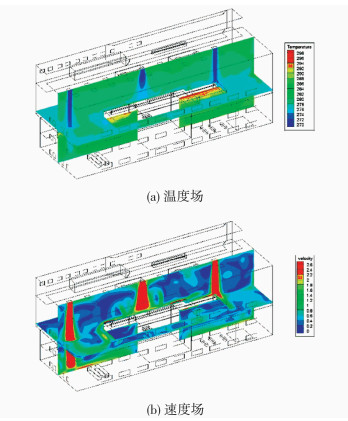
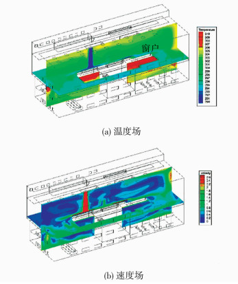
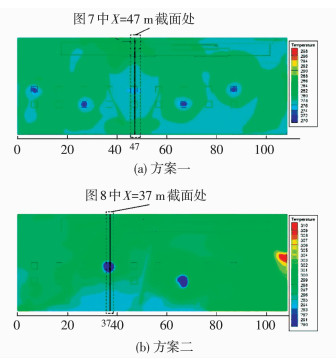
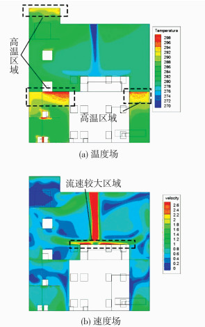
两种方案的速度场与温度场整体分布如图 3、4所示,铅垂切面为Y=18.5 m处的风口断面,Z=18 m的水平切面为工作层平台以上1.5 m处(即人体所感受的平台)的模拟结果.为了清晰地表示出两种方案在风机反转情况下的射流影响情况,给出了汽机房上层Z=23 m剖面处的温度与速度分布模拟结果,如图 5、6所示.图 7为方案一在X=47 m处、图 8为方案二在X=37 m处,屋顶风机出风口断面处的速度场与温度场分布细部描述.
|
图 3 方案一整体模拟结果 Figure 3 Global simulation results of scheme 1 |
|
图 4 方案二整体模拟结果 Figure 4 Global simulation results of scheme 2 |
|
图 5 汽机房Z=23 m处温度分布 Figure 5 Temperature distribution when Z=23 m |

|
图 6 汽机房Z=23 m处速度分布 Figure 6 Velocity distribution when Z=23 m |
|
图 7 方案一X=47 m处细部模拟结果 Figure 7 Detailed results of scheme 1 when X=47 m |

|
图 8 方案二X=37 m处细部模拟结果 Figure 8 Detailed results of scheme 2 when X=37 m |
两种方案由于通风量的不同,即带来的冷风侵入耗热量不同,机房内平均温度相差20.84 ℃.方案一中机房内部大部分区域温度在5~10 ℃,显然能满足机房内最低温度5 ℃的要求[11-12](由于该建筑不是民用建筑,不需满足采暖温度≥18 ℃的要求),且各平台温度分布基本符合要求.方案二汽机房内平均温度30.13 ℃,由于模拟工况为设计工况,实际工况只能比设计工况恶劣,且方案二运行2台风机,单台风机功率15 kW,从节能的角度考虑,方案二要优于方案一.因此,综合考虑建议其他3台屋顶风机为备用风机,交替运行.
由图 3、4和图 7、8可以看出,由于风机风速过大,导致射流气流直接与运转层平台相碰撞,形成自中间向两边的漩涡,这样的气流组织会带来以下两点不利影响:运转层风速大,给人带来吹风感从而引起不适;送风气流没有如预期的先和机房上部热空气均匀混合,再将热量送往下部,易造成机房内部局部过冷或过热.
通过模拟结果可以看出,方案二虽优于方案一,但两方案的气流组织均存在一些不理想因素,因此,需要针对气流组织进行优化设计,提出汽机房自平衡通风采暖优化方案.
3 汽机房自平衡通风采暖优化为了使气流组织更加合理,采用均布射流风口代替风机直接射流,同时在前述模拟结果上优化网格,对两方案进行优化设计.
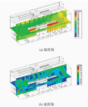
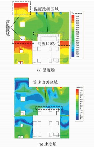
图 9为汽机房自平衡通风采暖优化方案的温度场与速度场分布,图 10为在射流口断面的温度场与速度场分布.可以看出,优化方案的温度场较前述两种方案有了很大改观.在运转层平台上,温度分布均匀.射流口的气流能较好地与机房上部热空气均匀混合,并将热量送到运转层平台.而运转层平台的下部尤其是汽轮机下部空间由于缺少空气流通,局部温度较高.在实际工程中,可以考虑增加工作层平台区域的格栅面积,并在图中高温区布置诱导风机.
|
图 9 优化方案整体模拟结果 Figure 9 Global results of optimization scheme |
|
图 10 优化方案X=49 m处温度场与速度场 Figure 10 Temperature and velocity distribution of optimization scheme when X=49 m |
图 11为底层与工作层平台温度场分布,表 5为3种方案的温度分布具体值.可以看出,各区域平均温度均满足采暖室内温度要求.汽机房内散热设备(热源)多布置于中部和中部偏右的区域,所以,汽机房右边整体温度要高于左边.由于本文考虑为设计工况下的模拟,在实际工况发生改变时,机房左边易产生温度较低的情况,需设置少量采暖设备以保证其温度需求.

|
图 11 优化方案各层温度场 Figure 11 Temperature distribution at different layer of optimization scheme |
| 表 5 3种方案汽机房温度分布 Table 5 Temperature distribution of turbine house with three schemes |
1) 在合理的气流组织设计前提下,将屋顶风机用于冬季供暖的方案是可行的,可减少汽机房内部分采暖散热器的设置.
2) 方案一与方案二都能满足冬季采暖需求,但从节能的角度应选用方案二,满足采暖需求的同时减少通风量,并降低总体风机电耗.
3) 直接射流的方案不能有效改善垂直温度梯度分布,布置均布风口代替风机直接射流能使上部热空气与射流气流更好地混合,同时改善工作层平台处的气流组织,使速度场分布更加均匀,达到较好的采暖效果.
| [1] |
包民业, 朱启振, 韩磊, 等. 夏季通风屋顶风机用于改善冬季供暖效果的设计及运行[J]. 暖通空调, 2005, 35(11): 50-55. BAO Minye, ZHU Qizheng, HAN Lei, et al. Heating effect improvement by roof ventilators in a large workshop[J]. Hv & Ac, 2005, 35(11): 50-55. |
| [2] |
DU Guofu, LEI Meiying, CHEN Xi, et al. Theindoor thermal environment simulation and testing validation of a power plant turbine room in extreme cold area[J]. Procedia Engineering, 2016, 146: 632-639. DOI:10.1016/j.proeng.2016.06.418 |
| [3] |
LINDEN P F. The fluid mechanics of naturalventilation[J]. Annual Review of Fluid Mechanics, 2003, 31(31): 309-335. |
| [4] |
HEISELBERG P, LI Y, ANDERSEN A, et al. Experimental and CFD evidence of multiple solutions in a naturally ventilated building[J]. Indoor Air, 2004, 14(1): 43-54. DOI:10.1046/j.1600-0668.2003.00209.x |
| [5] |
WANG Haidong, HUANG Chen, CUI Yezan, et al. Research on a secondary airflow-relay system to improve ventilation performance of nozzle supply in large space buildings[J]. Procedia Engineering, 2015, 121(6): 816-823. |
| [6] |
谢良珊. 常规岛主厂房通风模式优化与数值模拟的研究[D]. 上海: 东华大学, 2012. XIE Liangshan. Numerical simulation and optimization of ventilation mode in main power house for conventional island[D]. Shanghai: Donghua University, 2012. http://www.wanfangdata.com.cn/details/detail.do?_type=degree&id=Y2265327 |
| [7] |
ROHDIN P, MOSHFEGH B. Numerical predictions of indoor climate in large industrial premises. A comparison between different k-ε, models supported by field measurements[J]. Building & Environment, 2007, 42(11): 3872-3882. |
| [8] |
康逸翁, 王阳, 綦建国, 等. 先进压水堆核电厂汽机房通风系统模拟研究[J]. 暖通空调, 2017, 47(2): 36-44. KANG Yiweng, WANG Yang, QI Jianguo, et al. Numerical simulation on ventilation scheme in a turbine building of advanced nuclear power plant[J]. Hv & Ac, 2017, 47(2): 36-44. |
| [9] |
阎超. 计算流体力学方法及应用[M]. 北京: 北京航空航天大学出版社, 2006. YAN Chao. Computational fluid dynamics method and its application[M]. Beijing: Beihang University Press, 2006. |
| [10] |
吕宇航. 福清核电站常规岛汽机房通风系统的数值模拟[D]. 上海: 东华大学, 2009. LU Yuhang. Numerical Simulation on air distribution in convention island turbine machine room of Fuqing nuclear power station[D]. Shanghai: Donghua University, 2009. http://cdmd.cnki.com.cn/Article/CDMD-10255-2009109819.htm |
| [11] |
电力规划设计总院. 发电厂供暖通风与空气调节设计规范: DL/T 5035-2016[S]. 北京: 中国计划出版社, 2016. Electric Power Planning & Engineering Institute. Code for design of heating ventilation and air conditioning of power plant: DL/T 5035-2016[S]. Beijing: China Planning Press, 2016. |
| [12] |
李善化, 康慧, 孙相军, 等. 火力发电厂及变电所采暖通风空调设计手册[M]. 北京: 中国电力出版社, 2001. LI Shanhua, KANG Hui, SUN Xiangjun, et al. Handbook of heating, ventilation and air conditioning design for thermal power plants and substations[M]. Beijing: China Electric Power Press, 2001. |
 2018, Vol. 50


