2. 上海大学 风工程和气动控制研究中心,上海 200444;
3. 河南工业大学 土木建筑学院,郑州 450001
2. Wind Engineering and Aerodynamic Flow Control Research Center, Shanghai University, Shanghai 200444, China;
3. College of Civil Engineering and Architecture, Henan University of Technology, Zhengzhou 450001, China
涡激振动现象时常发生,并易对结构造成疲劳破坏,因而受到广泛关注[1].与单方柱相比,双方柱涡激振动的影响因素众多[2],其干扰机理尚不明确.
对于固定串列双方柱绕流,Sohankar[3]将串列双方柱的柱间流态分为单一钝体流态、剪切层再附流态(L/B=2~4,其中L为柱心间距,B为方柱边长)和双涡脱流态三类.学者将双方柱从剪切层再附流态向双涡脱流态转变的柱心间距比称为临界间距比,Sohankar[3]得出的临界间距比为L/B=4.Yen等[4]发现双方柱在剪切层再附流态时的绕流场特性非常复杂,并得出双方柱的临界间距比为L/B=3~5.
对于单方柱涡激振动,Zhao等[5]发现当流向角为0°时,单方柱在低雷诺数下并无明显的“锁定”现象.Sen等[6]得出低质量比的单方柱会出现“弱锁定”现象,即方柱在振动锁定区内的振动频率与自振频率的比值fy/fn远小于1.0;“弱锁定”现象发生时,单方柱常有大幅横流向振动;随着质量比增加,方柱的“弱锁定”现象会消失,而出现“锁定”现象,即fy/fn≈1.0.
针对双方柱振动问题,往年研究并不充分.Kumar等[7-8]发现在上游方柱运动、下游方柱固定的情况下,当两方柱的柱心间距较小(L/B=1.25)且处于串列布置时,上游方柱出现横流向最大振幅.Mithun等[9]则在雷诺数Re=100时,通过固定方柱振幅、改变横流向振动频率,研究了串列方柱的气动力和流场结构特征,发现当L/B=2和3时,下游方柱的升力随时间推移变化紊乱.Pillalamarri等[10-11]则在Re=200、m*=m/(ρB2)=5(m为方柱质量,ρ为流体密度)和L/B=4情况下,对上游方柱固定、下游方柱运动的串列双方柱进行了数值模拟研究.Guan等[12]则在Re=200、m*=10时,研究了刚性连接并列双方柱的涡激振动特性.
学者对双方柱在中小间距和临界间距时的振动问题均较为关注,未见到在此间距下,研究上、下游方柱均可自由振动的双方柱涡激振动的相关文献.本文在Re=150时,对L=2B和4B的串列双方柱涡激振动进行了数值研究.
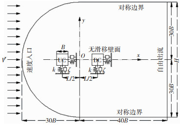
1 数值方法 1.1 计算模型和控制方程将双方柱涡激振动简化为质量-弹簧-阻尼系统(见图 1),图中UC和DC分别表示上、下游方柱,V为均匀来流速度.入口边界与上下边界距原点O均为30B;出口边界距原点O为40B.
|
图 1 计算模型和计算域 Fig. 1 Sketch of computational model and computational domain |
对于流体域,假定方柱周围流场为二维不可压缩流体,其连续方程和N-S方程分别为:
| $ \frac{{\partial u}}{{\partial x}} + \frac{{\partial v}}{{\partial y}} = 0, $ | (1) |
| $ \rho \frac{{Du}}{{Dt}} = \rho {F_x} - \frac{{\partial p}}{{\partial x}} + \mu \left( {\frac{{{\partial ^2}u}}{{\partial {x^2}}} + \frac{{{\partial ^2}u}}{{\partial {y^2}}}} \right), $ | (2) |
| $ \rho \frac{{Dv}}{{Dt}} = \rho {F_y} - \frac{{\partial p}}{{\partial y}} + \mu \left( {\frac{{{\partial ^2}v}}{{\partial {x^2}}} + \frac{{{\partial ^2}v}}{{\partial {y^2}}}} \right), $ | (3) |
式中:p为流体压力,μ为黏性系数,u、v分别为x、y方向的速度,Fx、Fy分别为流体在x、y方向的体力.
对于固体域,两个方柱均考虑顺流向和横流向运动,其控制方程为:
| $ m\frac{{{{\rm{d}}^2}X}}{{{\rm{d}}{t^2}}} + c\frac{{{\rm{d}}X}}{{{\rm{d}}t}} + kX = {F_{\rm{D}}}\left( t \right), $ | (4) |
| $ m\frac{{{{\rm{d}}^2}Y}}{{{\rm{d}}{t^2}}} + c\frac{{{\rm{d}}Y}}{{{\rm{d}}t}} + kY = {F_{\rm{L}}}\left( t \right), $ | (5) |
式中:X和Y分别为方柱的顺流向与横流向位移,c和k分别为结构阻尼与刚度,FD(t)和FL(t)分别为作用在方柱上的顺流向与横流向流动力.
数值计算中,对于流体域,采用层流模型,通过SIMPLEC法求解速度与压力耦合,通过二阶精度离散格式求解式(2)、(3);对于固体域,式(4)、(5)的求解采用四阶龙格库塔方法.网格更新采用弹簧光滑法.
数值模拟参数Re=150,L=2B和4B,m*=10;为节省计算资源,c取0;折减速度Vr=V/(fnB)=1~12,其中结构自振频率fn在x和y两个方向保持一致,且在计算中保持V不变,而通过改变fn实现不同Vr的计算.由于L=2B的双方柱在Vr>13时出现相互碰撞,因此本文仅分析Vr=1~12的工况.
1.2 边界条件及网格划分图 1还给出了网格模型的边界条件,本文将入口边界、两侧壁面、出口边界和方柱表面分别设为速度入口、对称边界、自由出流和无滑移壁面.
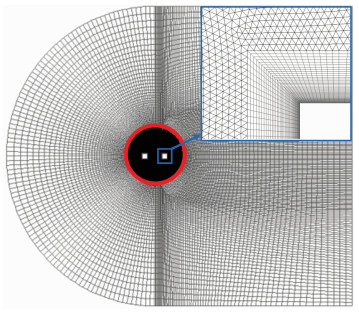
双方柱网格方案见图 2,对计算域网格进行分块处理,在方柱近壁面内采用结构化网格;圆形框内的网格采用非结构化,框外则为结构化.通过加密距离方柱表面较近处的网格来捕捉其周围复杂的流场,本文也考虑了近壁面最小网格厚度的影响(见表 1).为减小网格更新计算量,仅将圆形框区域设定为动网格区域.
|
图 2 网格方案 Fig. 2 Grid scheme |
| 表 1 结果验证与网格参数 Tab. 1 Grid parameters and results verification |
为验证计算模型的合理性,分别对单方柱绕流和涡激振动进行网格独立性检验和结果验证.
2.1 单方柱绕流的结果验证以雷诺数为150的静止单方柱绕流为算例,进行了网格和步长独立性验证,并与文献结果进行对比(表 1),表中St、CL, rms、CD, mean分别为斯特罗哈数、脉动升力系数和平均阻力系数,A1~A4和B1~B3工况分别为周向和径向网格独立性检验,Z1~Z3工况为无量纲时间步(Δt*=ΔtV/B,Δt为计算时间步长)独立性验证.可见,本文所有工况的计算结果较为接近,也与文献结果吻合较好.考虑到模拟精度和计算效率,后续网格模型均采用A3工况的参数.
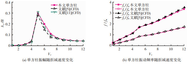
2.2 单方柱涡激振动的结果验证采用A3工况的网格,将Re=100、m*=3的单方柱涡激振动的计算结果与文献进行比较(见图 3),图中Ay/B(Ay=(Ymax-Ymin)/2)、fx/fn和fy/fn分别为横流向无量纲振幅、顺流向振动频率比和横流向振动频率比,其中fx、fy分别为方柱的顺、横流向振动频率;Ymin、Ymax分别为横流向最小位移和最大位移.由图 3可知本文结果非常吻合文献结果.
|
图 3 方柱涡激振动结果验证 Fig. 3 Results verification on vortex-induced vibration of square cylinder |
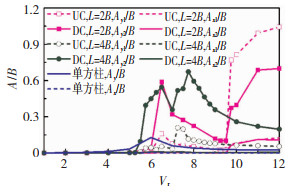
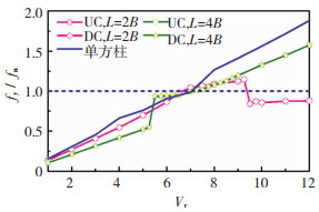
图 4、5为双方柱无量纲振幅Ay/B、Ax/B(Ax=(Xmax-Xmin)/2)和振动频率比fy/fn随Vr的变化曲线,为便于比较,图中还给出了单方柱的计算结果,其中Xmin和Xmax为顺流向最小位移和最大位移;上游柱(UC)参数脚标设为1,下游柱(DC)设为2.可见:
|
图 4 双方柱振幅随折减速度的变化 Fig. 4 Variations of amplitude of two square cylinders with reduced velocity |
|
图 5 双方柱横流向振动的频率比 Fig. 5 Variations of relative vibration frequency of two square cylinders |
1) 不同柱心间距双方柱和单方柱的振动均以横流向为主.与双方柱相比,单方柱Ay较小且无明显的“弱锁定”和“锁定”现象,这与文献[5]结论相同.
2) 当L=2B时,上下游方柱的振动锁定区为Vr=9.75~12,并伴有“弱锁定”现象发生,其对应的fy/fn≈0.87;两方柱在振动锁定区内出现Ay最大值,其值分别为Ay1=1.04B和Ay2=0.70B.当L增大至4B时,上游方柱无大幅横流向振动,因此未发生“锁定”和“弱锁定”现象,而下游方柱的振动锁定区为Vr=5.5~6.5,且发生“锁定”现象,对应的fy/fn≈0.94;两方柱Ay最大值均出现在振动锁定区外,其值分别为Ay1=0.21B和Ay2=0.67B.
值得注意的是,不同柱心间距的下游方柱在振动锁定区外也存在大幅横流向振动,其振动区域分别为Vr=6.5~7(L=2B)和Vr=7~9(L=4B),下文将对此进一步分析.此外,本文将下游方柱的横流向振幅曲线与文献[11]进行比较.发现随着Vr的增加,文献[11]的下游方柱横流向振幅也会出现两个峰值,但振幅与本文差异较大,这可能是上游方柱运动状态的不同造成的.
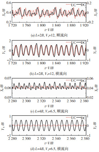
为进一步研究双方柱的振动特性,图 6给出了双方柱在振动锁定区内的位移时程.可见,对于顺流向,L=2B和4B的上下游方柱的振动相位随时间推移而不断变化.对于横流向,L=2B的两方柱振动相位为同相位,其相位角ψ≈38°;L=4B的两方柱振动相位则为反相位,其ψ≈152°.
|
图 6 振动锁定区内上下游方柱位移时程 Fig. 6 Time history curves of displacement of two square cylinders in vibration lock-in region |
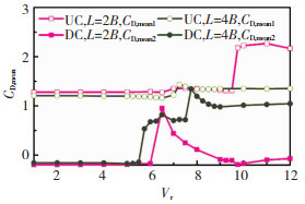
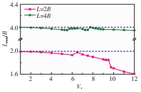
当柱心间距随Vr变化发生改变时,将对双方柱的振动响应和流场结构产生影响,因此,图 7、8给出了双方柱CD, mean和平均柱心间距Lmean随Vr的变化规律.
|
图 7 平均阻力系数随折减速度的变化 Fig. 7 Variations of CD, mean with reduced velocity |
当L=2B时,在振动锁定区(Vr=9.75~12)内,CD, mean1值为正且数值急剧增加,致使上游方柱沿顺流向产生较大偏移;此时,上游方柱对下游方柱的“遮挡”作用[16]造成CD, mean2 < 0,致使下游方柱逆流向上产生偏移,最终导致Lmean的急剧减小(见图 8).
|
图 8 平均柱心间距随折减速度的变化 Fig. 8 Variations of Lmean with reduced velocity |
当L=4B时,CD, mean1随Vr增加基本不变,而CD, mean2随Vr的增加逐渐接近CD, mean1,致使上下游方柱顺流向偏移量相近,从而导致Lmean基本不变.
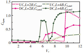
3.2.2 脉动升力系数图 9为CL, rms随Vr的变化曲线,可见,当L=2B时,在振动锁定区内(Vr=9.75~12),两方柱CL, rms迅速增加,且CL, rms1>CL, rms2,因而两方柱出现Ay最大值,且上游方柱Ay最大值大于下游方柱;下游方柱在振动锁定区外(Vr=6.5~7)也会有较大的CL, rms2,此时下游方柱的fy与fn较为接近(见图 5),其升力更易激励下游方柱振动,因而出现大幅横流向振动.当L=4B时,上游方柱的CL, rms1随Vr增加变化幅度较小;下游方柱在振动锁定区内、外均会出现较大的CL, rms2,其中在振动锁定区外(Vr=7~9),下游方柱的fy与fn较为接近(见图 5),因此出现较大横流向振幅.
|
图 9 脉动升力系数随折减速度的变化 Fig. 9 Variations of CL, rms with reduced velocity |
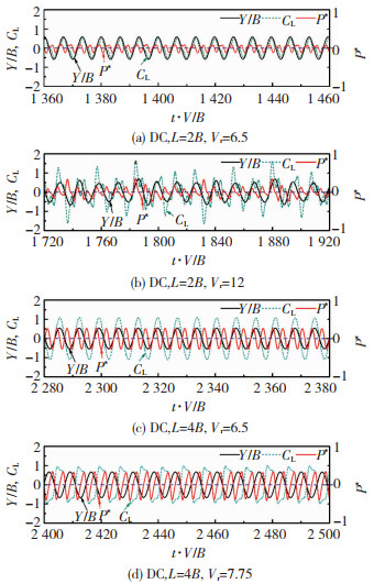
本节将结合瞬时能量输入过程,分析下游方柱Ay2在各振动区达到极值时的工况.图 10为下游方柱能量输入、升力系数与横流向位移的时程.其中P*=CL(t)v(t)/V为无量纲功率,v(t)为方柱横流向运动速度.
|
图 10 下游方柱的升力系数、横流向位移和能量输入时程 Fig. 10 Time history curves of energy input, cross-flow displacement, and lift coefficient of downstream square cylinder |
对于振动锁定区外的情况(图 10(a)、(d)),L=2B和4B时,下游方柱的CL与Y随时间推移均呈稳定的相位变化,致使升力对下游方柱能量输入稳定.且此时下游方柱的fy与fn相近,其升力极易激励下游方柱振动,因而下游方柱横流向振幅在振动锁定区外出现明显极值.
对于振动锁定区内的情况(图 10(b)、(c)),当L=2B时,虽然下游方柱CL具有较大的幅值,但由于上游方柱尾涡的影响,下游方柱CL的周期性较弱,造成CL与Y的相位不断变化,从而扰乱并减弱了升力对下游方柱的能量输入,因此,下游方柱横流向振幅虽达到最大值,但小于上游方柱.当L=4B时,下游方柱的CL与Y相位稳定,且CL出现较大幅值,造成其对下游方柱稳定输入强劲能量,因而下游方柱在振动锁定区内出现大幅横流向振动.
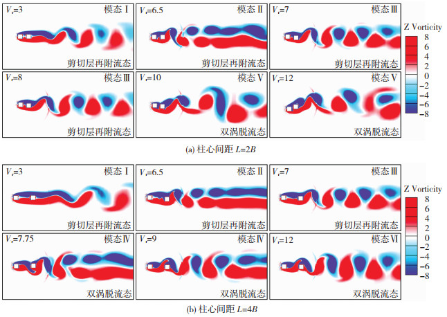
3.4 流场结构特征图 11为双方柱尾流模态及柱间流态随Vr增加的演变过程.可见,共出现柱间流态2种、尾流模态6种.表 2归纳了双方柱尾流模态与柱间流态的关系.
|
图 11 双方柱柱间流态和尾流模态 Fig. 11 Wake modes and flow regimes of two square cylinders |
| 表 2 不同柱心间距的柱间流态和尾流模态 Tab. 2 Wake modes and flow regimes of two square cylinders with different spacing |
在剪切层再附流态内,L=2B和4B时的双方柱尾流模态均为模态Ⅰ~Ⅲ.其中模态Ⅰ下游方柱背风面存在较长的尾流;模态Ⅱ和模态Ⅲ分别为剪切层再附流态内的平行涡街模态和“2S”模态.当方柱处于双涡脱流态时,L=2B时仅出现模态Ⅴ,此时下游方柱背风面尾涡极不稳定;L=4B的则为模态Ⅳ和Ⅵ,其分别为双涡脱流态内的平行涡街模态和“2S”模态.
结合上文知,L=2B时的双方柱振动锁定区(Vr=9.75~12)出现在双涡脱流态内,此时的尾流为模态Ⅴ;L=4B时的下游方柱振动锁定区(Vr=5.5~6.5)出现在剪切层再附流态内,此时的尾流为模态Ⅱ.两种柱心间距的下游方柱横流向振幅在振动锁定区外也有明显极值,其尾流分别为模态Ⅱ(L=2B,Vr=6.5)和Ⅳ(L=4B,Vr=8.5).
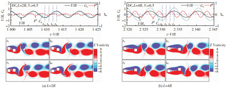
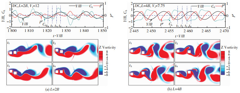
3.5 流固耦合机制结合图 10,为研究导致下游方柱振动的流固耦合机制,图 12、13给出了下游方柱出现大幅振动时的瞬时涡量图及对应的能量输入时程.其中,图 12为剪切层再附流态下,两种柱心间距的Ay2分别在振动锁定区内(L=4B)和区外(L=2B)出现明显极值时的典型工况;图 13为双涡脱流态下,两种柱心间距的Ay2分别在振动锁定区内(L=2B)和区外(L=4B)出现明显极值时的典型工况
|
图 12 剪切层再附流态内典型工况的瞬时涡量图 Fig. 12 Instantaneous vorticity contours under typical conditions in reattachment regime |
|
图 13 双涡脱流态内典型工况的瞬时涡量图 Fig. 13 Instantaneous vorticity contours under typical conditions in co-shedding regime |
见图 12,L=2B和4B的上游方柱均未见旋涡脱落,下游方柱的大幅横流向振动主要由背风面卷起的强烈旋涡引起;此外,下游方柱的大幅横流向振动导致旋涡的横流相间距变大,因而形成了模态Ⅱ.
见图 13,L=2B时的Lmean急剧减小,致使下游方柱流场更易受上游方柱尾涡影响,造成下游方柱升力对其运动进行不稳定的能量输入,同时也导致下游方柱的尾涡极不稳定(模态Ⅴ).当L=4B时,由于两方柱间距较大,上游方柱尾涡会撞击下游方柱迎风面,并一分为二,其中一个旋涡的强度随时间流逝而减弱(t1时刻),而另一旋涡则和下游方柱脱落的涡发生融合(t1和t2时刻),从而增强了升力对下游方柱的能量输入,故而促进横流向振动.由于结构与流场的耦合作用,大幅横流向振动拉大了旋涡的横流向间距,最终形成模态Ⅳ.
4 结论通过对两种典型柱心间距的串列双方柱涡激振动进行数值研究,得到如下结论:
1) L=2B时,上、下游方柱均在双涡脱流态内发生“弱锁定”现象,即振动锁定区内的振动频率锁定值fy/fn远小于1.0.L=4B时,仅下游方柱在剪切层再附流态内发生“锁定”现象.
2) 不同柱心间距双方柱均以横流向为主.L=2B时的上游方柱横流向最大振幅大于下游方柱,且均出现在振动锁定区内.L=4B时的上游方柱横流向最大振幅远小于下游方柱,且均出现在振动锁定区外.各柱心间距下游方柱在振动锁定区内、外均有大幅横流向振动.
3) L=2B时的上游方柱平均阻力系数在振动锁定区内出现激增,而下游方柱平均阻力系数在振动锁定区内为负值,导致两方柱平均柱心间距急剧减小.各柱心间距的下游方柱在振动锁定区内、外均会有较大的脉动升力.
4) 不同柱心间距的双方柱随折减速度变化共出现了2种柱间流态,即剪切层再附流态和双涡脱流态,还出现了6种尾流模态.其中,L=2B和4B时的下游方柱均在双涡脱流态内出现横流向最大振幅,其中,L=2B时平均柱心间距的急剧减小致使上游方柱尾流对下游方柱的影响更为复杂,扰乱了下游方柱升力对其运动的能量输入,使得下游方柱尾流中的旋涡极不稳定;L=4B时上、下游方柱脱落的旋涡相融合,增强了升力对下游方柱的能量输入,增大了横流向振幅,导致旋涡的横流向间距变大,也使得下游方柱的尾流为双涡脱流态内的平行涡街模态.
| [1] |
BEARMAN P W. Vortex shedding from oscillating bluff bodies[J]. Annual Review of Fluid Mechanics, 1984, 16(1): 195. DOI:10.1146/annurev.fl.16.010184.001211 |
| [2] |
BAILEY P A, KWOK K C S. Interference excitation of twin tall buildings[J]. Journal of Wind Engineering and Industrial Aerodynamics, 1985, 21(3): 323. DOI:10.1016/0167-6105(85)90043-1 |
| [3] |
SOHANKAR A. A numerical investigation of the flow over a pair of identical square cylinders in a tandem arrangement[J]. International Journal for Numerical Methods in Fluids, 2012, 70(10): 1244. DOI:10.1002/fld.2739 |
| [4] |
YEN S C, SAN K C, CHUANG T H. Interactions of tandem square cylinders at low Reynolds numbers[J]. Experimental Thermal and Fluid Science, 2008, 32(4): 927. DOI:10.1016/j.expthermflusci.2007.07.001 |
| [5] |
ZHAO Ming, CHENG Liang, ZHOU Tongming. Numerical simulation of vortex-induced vibration of a square cylinder at a low Reynolds number[J]. Physics of Fluids, 2013, 25(2): 023603. DOI:10.1063/1.4792351 |
| [6] |
SEN S, MITTAL S. Effect of mass ratio on free vibrations of a square cylinder at low Reynolds numbers[J]. Journal of Fluids and Structures, 2015, 54: 661. DOI:10.1016/j.jfluidstructs.2015.01.006 |
| [7] |
KUMAR R A, GOWDA B H L. Vortex-induced vibration of a square cylinder without and with interference[J]. Journal of Fluids and Structures, 2006, 22(3): 345. DOI:10.1016/j.jfluidstructs.2005.11.006 |
| [8] |
KUMAR R A, GOWDA B H L, SOHN C H. Interference excitation of a square section cylinder[J]. Journal of Mechanical Science and Technology, 2008, 22(3): 599. DOI:10.1007/s12206-007-1207-2 |
| [9] |
MITHUN M G, TIWARI S. Flow past two tandem square cylinders vibrating transversely in phase[J]. Fluid Dynamics Research, 2014, 46(5): 055509. DOI:10.1088/0169-5983/46/5/05550 |
| [10] |
ZHAO G M, PILLALAMARRI N R, MYSA R C, et al. Flow-induced vibrations of single and tandem square columns[C]//Proceedings of ASME 2015 34th International Conference on Ocean, Offshore and Arctic Engineering. St. John's, Newfoundland: American Society of Mechanical Engineers Digital Collection, 2015: 416
|
| [11] |
JAIMAN R K, PILLALAMARRI N R, ZHAO G M. A stable second-order partitioned iterative scheme for freely vibrating low-mass bluff bodies in a uniform flow[J]. Computer Methods in Applied Mechanics and Engineering, 2016, 301: 187. DOI:10.1016/j.cma.2015.12.019 |
| [12] |
GUAN M Z, JAIMAN R K. Vortex-induced vibration of two side-by-side square cylinders with combined translational motions[J]. Journal of Fluids and Structures, 2017, 69: 265. DOI:10.1016/j.jfluidstructs.2016.12.010 |
| [13] |
SINGH A P, DE A K, CARPENTER V K, et al. Flow past a transversely oscillating square cylinder in free stream at low Reynolds numbers[J]. International Journal for Numerical Methods in Fluids, 2009, 61(6): 658. DOI:10.1002/fld.1979 |
| [14] |
YOON D H, YANG K S, CHOI C B. Flow past a square cylinder with an angle of incidence[J]. Physics of Fluids, 2010, 22(4): 043603. DOI:10.1063/1.3388857 |
| [15] |
SHARMA A, ESWARAN V. Heat and fluid flow across a square cylinder in the two-dimensional laminar flow regime[J]. Numerical Heat Transfer, Part A: Applications, 2004, 45(3): 247. DOI:10.1080/10407780490278562 |
| [16] |
及春宁, 陈威霖, 黄继露, 等. 串列双圆柱流致振动的数值模拟及其耦合机制[J]. 力学学报, 2014, 46(6): 862. JI Chunning, CHEN Weilin, HUANG Jilu, et al. Numerical investigation on flow-induced vibration of two cylinders in tandem arrangements and its coupling mechanisms[J]. Chinese Journal of Theoretical and Applied Mechanics, 2014, 46(6): 862. DOI:10.6052/0459-1879-14-118 |
 2020, Vol. 52


