2. 天津市非线性动力学与控制重点实验室(天津大学), 天津 300354;
3. 天津大学 力学国家级实验教学示范中心,天津 300354
2. Tianjin Key Laboratory of Nonlinear Dynamics and Control (Tianjin University), Tianjin 300354, China;
3. National Demonstration Center for Experimental Mechanics Education, Tianjin University, Tianjin 300354, China
为了提高推重比、改善气动稳定性,现代航空发动机多采用双转子结构.中介轴承作为联系高低压转子的关键部件,由于工作时内外圈转速大、环境温度高、润滑条件难以保证,因此也是双转子系统中的薄弱环节.随着轴承零件几何误差和工艺缺陷的降低,润滑对轴承及转子系统振动的影响已日显重要.润滑油在轴承中将钢球和滚道两接触体分离,不仅可以起到降温的作用,还会改变转子系统的振动特性.因此分析中介轴承处的弹流润滑作用对航空发动机双转子系统动力学特性的影响是非常必要的.
国内外学者运用多种建模方法以及不同的数值求解手段,针对中介轴承-双转子系统动力学响应,进行了一系列研究. Ferraris等[1]利用拉格朗日方程建立双转子模型,利用有限元方法预测系统动力学行为.Chen[2]建立转子-球轴承-机匣耦合动力学模型,转子和机匣系统用有限元方法建模,支承系统采用集中参数法建模,用Newmark-β方法以及翟方法对系统响应进行求解,结果表明提出的模型可有效仿真航空发动机的振动特性.Hu等[3]建立了五自由度双转子模型,采用Runge-Kutta-Fehlberg算法进行求解.此外,白雪川[4]对反向旋转双转子系统,开展了机动飞行实验.张天程等[5]分析了碰摩状态下,双转子系统的弯曲振动和扭转振动.Wang等[6]重点考虑了中介轴承对双转子系统动力学特性的影响.Gao等[7]建立了中介轴承的局部缺陷模型并对双转子系统的非线性响应进行了分析.Sun等[8]用MHB-AFT方法分析了碰摩情况下双转子系统的稳态响应.Hou等[9]应用HB-AFT方法对双转子系统中的主共振进行了研究.
弹性流体动力润滑(Elastohydrodynamic lubrication, EHL),简称弹流润滑,是将Reynolds润滑理论和Hertz弹性接触理论相结合,研究滚动或滚滑条件下弹性体之间的流体动力润滑特性.在球轴承中,滚珠和滚道之间一般处于弹流润滑状态[10].张彤等[11]以球轴承为研究对象,求解了滚动体和内外圈在弹流润滑状态下的刚度和阻尼,分析了轴承不同转速和游隙对转子系统动态特性的影响,研究表明具有动态刚度和阻尼的轴承-转子系统动力学特性更加复杂.张俊红等[12]研究了弹流润滑作用下,转子-滚动轴承系统在碰摩和不对中耦合故障状态下的动力学响应,并在实验台进行验证,结果表明考虑弹流润滑理论的模型比未考虑弹流润滑理论的模型更能准确体现耦合故障系统的振动响应.王占彬等[13]基于点接触的弹流润滑理论,利用数值方法求解了轴承-转子系统的动力学微分方程,通过不同参数条件下的轴心轨迹、相图、分岔图等,分析了转子系统的动力学特性.田晶等[14]考虑了弹流润滑影响和时变位移激励,提出一种带局部缺陷的中介轴承动力学模型,通过实验验证结果表明,提出模型能准确模拟中介轴承在不同状态和不同缺陷尺寸下的振动响应.
上述研究大都针对弹流润滑作用对轴承或单转子系统的影响,而双转子系统中介轴承处普遍存在弹流润滑作用.目前关于考虑中介轴承弹流润滑作用时双转子系统动力学特性的研究较为欠缺.
本文以航空发动机双转子系统为研究对象,建立了考虑中介轴承弹流润滑影响的中介轴承-双转子系统动力学模型,采用龙格库塔法求解,对双转子系统的动力学特性进行分析,通过与不考虑弹流润滑影响的双转子系统比较,研究了弹流润滑作用对双转子系统动力学特性的影响.
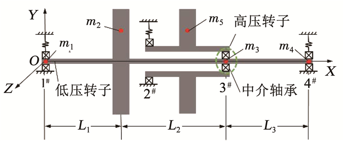
1 系统建模 1.1 双转子系统建模如图 1所示,建立含中介轴承的4点支承航空发动机双转子系统模型.
|
图 1 双转子系统模型 Fig. 1 Schematic of dual rotor system model |
低压系统包括无质量的弹性转轴、刚性圆盘和1#、4#支承,轴颈质量分别为m1、m3和m4,轴段L1、L2和L3对应的刚度为k5、k6和k7,圆盘质量为m2,圆盘偏心距为s2,1#、4#支承处采用滚动轴承和弹性支承结构,简化为弹簧阻尼系统,刚度和阻尼分别为k1、k4和c1、c4.高压转子考虑为刚性转子,因此高压系统包括无质量的刚性转轴、刚性圆盘和2#支承,圆盘质量为m5,圆盘偏心距s5,2#支承处同样采用滚动轴承加弹性支承结构,简化后的刚度和阻尼为k2和c2.高低压转子定转速比反向旋转,低压转子转速为ω1,高压转子转速为ω2.忽略圆盘的偏转和陀螺力矩,系统包括10个自由度.
根据转子动力学理论和集中质量法,得系统动力学方程:
| $ \boldsymbol{M} \ddot{\boldsymbol{q}}+\boldsymbol{C \dot { q }}+\boldsymbol{K} \boldsymbol{q}=\boldsymbol{F}. $ | (1) |
质量mi(i=1, 2, 3, 4, 5)对应的坐标为(zi, yi),系统的广义坐标矢量q为
| $ \boldsymbol{q}=\left\{\begin{array}{llllllllll} z_{1} & z_{2} & z_{3} & z_{4} & z_{5} & y_{1} & y_{2} & y_{3} & y_{4} & \left.y_{5}\right\}^{\mathrm{T}}. \end{array}\right. $ | (2) |
质量矩阵M、刚度矩阵K、阻尼矩阵C分别为:
| $ \boldsymbol{M}=\left[\begin{array}{cc} \boldsymbol{M}_{c} & 0 \\ 0 & \boldsymbol{M}_{c} \end{array}\right], \boldsymbol{K}=\left[\begin{array}{cc} \boldsymbol{K}_{z} & 0 \\ 0 & \boldsymbol{K}_{y} \end{array}\right], C=\left[\begin{array}{cc} \boldsymbol{C}_{z} & 0 \\ 0 & \boldsymbol{C}_{y} \end{array}\right], $ | (3) |
其中:
| $ \boldsymbol{M}_{c}=\left[\begin{array}{ccccc} m_{1} & 0 & 0 & 0 & 0 \\ 0 & m_{2} & 0 & 0 & 0 \\ 0 & 0 & m_{3} & 0 & 0 \\ 0 & 0 & 0 & m_{4} & 0 \\ 0 & 0 & 0 & 0 & m_{5} \end{array}\right], $ |
| $ \boldsymbol{K}_{z}=\boldsymbol{K}_{y}=\left[\begin{array}{ccccc} k_{1}+k_{5} & -k_{5} & 0 & 0 & 0 \\ -k_{5} & k_{5}+k_{6} & -k_{6} & 0 & 0 \\ 0 & -k_{6} & k_{6}+k_{7} & -k_{7} & 0 \\ 0 & 0 & -k_{7} & k_{4}+k_{7} & 0 \\ 0 & 0 & 0 & 0 & k_{2} \end{array}\right], $ |
| $ \boldsymbol{C}_{z}=\boldsymbol{C}_{y}=\left[\begin{array}{ccccc} c_{1}+c_{5} & -c_{5} & 0 & 0 & 0 \\ -c_{5} & c_{5}+c_{6} & -c_{6} & 0 & 0 \\ 0 & -c_{6} & c_{6}+c_{7} & -c_{7} & 0 \\ 0 & 0 & -c_{7} & c_{4}+c_{7} & 0 \\ 0 & 0 & 0 & 0 & c_{2} \end{array}\right]. $ |
广义力矢量F为
| $ \boldsymbol{F}=\boldsymbol{F}_{\mathrm{b}}+\boldsymbol{G}+\boldsymbol{F}_{\mathrm{s}} $ | (4) |
其中: Fb为中介轴承力矢量, 即
| $ \boldsymbol{F}_{\mathrm{b}}=\left\{0\quad 0 \quad F_{\mathrm{b} z} \quad 0 \quad-F_{\mathrm{b} z} \quad 0\quad 0 \quad F_{\mathrm{b}y}\quad 0\quad -F_{\mathrm{b}y}\right\}^{\mathrm{T}}, $ |
G为重力矢量,即
| $ \boldsymbol{G}=\left\{\begin{array}{llllllllll} 0 & 0 & 0 & 0 & 0 & -m_{1} g & -m_{2} g & -m_{3} g & -m_{4} g & -m_{5} g \end{array}\right\}^{\mathrm{T}}, $ |
Fs为不平衡力矢量, 即
| $ \boldsymbol{F}_{\mathrm{s}}=\left\{\begin{array}{llllllllll} 0 & \boldsymbol{F}_{\mathrm{s} 1} & 0 & 0 & \boldsymbol{F}_{\mathrm{s} 2} & 0 & \boldsymbol{F}_{\mathrm{s} 3} & 0 & 0 & \left.\boldsymbol{F}_{\mathrm{s} 4}\right\}^{\mathrm{T}}, \end{array}\right. $ |
| $ \boldsymbol{F}_{\mathrm{s} 1}=m_{2} s_{2} \omega_{1}^{2} \sin \left(\omega_{1} t\right), \boldsymbol{F}_{\mathrm{s} 2}=m_{5} s_{5} \omega_{2}^{2} \sin \left(\omega_{2} t\right), $ |
| $ \boldsymbol{F}_{\mathrm{s} 3}=m_{2} s_{2} \omega_{1}^{2} \cos \left(\omega_{1} t\right), \boldsymbol{F}_{\mathrm{s} 4}=m_{5} s_{5} \omega_{2}^{2} \cos \left(\omega_{2} t\right) . $ |
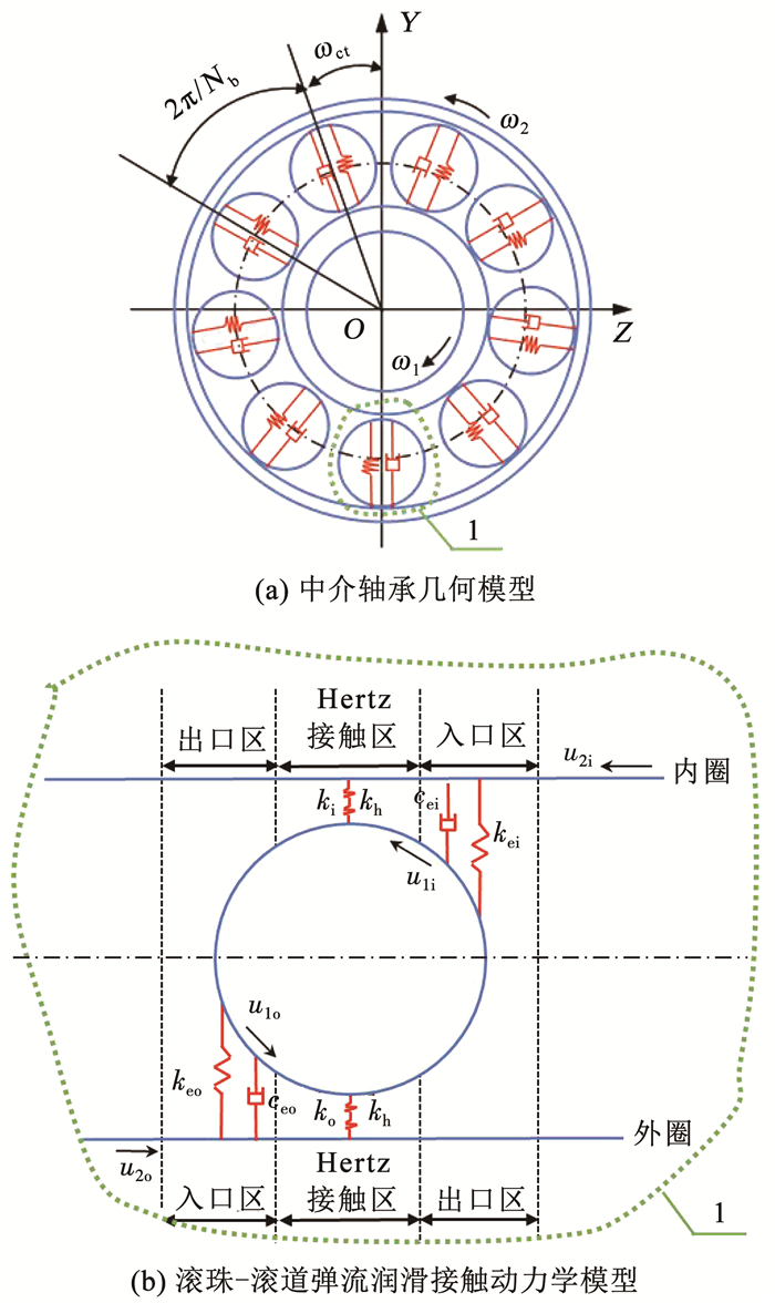
考虑中介轴承为滚珠轴承,理想中介轴承几何模型如图 2(a)所示,根据Hertz接触变形理论,球轴承的支反力可表示为[15]
| $ F=k \delta^{3 / 2}. $ | (5) |
|
图 2 考虑弹流润滑作用的中介轴承模型 Fig. 2 Intershaft bearing model considering EHL |
其中:k为接触刚度,δ为滚动体表面接触点的弹性变形量.
第j个滚动体的径向弹性接触变形δj可表示为
| $ \delta_{j}=\left(y_{\mathrm{i}}-y_{\mathrm{o}}\right) \cos \theta_{j}+\left(z_{\mathrm{i}}-z_{\mathrm{o}}\right) \sin \theta_{j}-\delta_{0} . $ | (6) |
式中:zi、zo、yi、yo分别为中介轴承内、外圈在水平和竖直方向的位移分量;δ0为中介轴承的径向间隙;θj为任一时刻滚动体的运动位置角度,可表示为:
| $ {{\theta _j} = {\omega _c}t + \frac{{{\rm{2 \mathsf{ π} }}}}{{{N_b}}}(j - 1),} $ | (7) |
| $ {{\omega _{\rm{c}}} = \frac{{{\omega _1}{R_{\rm{i}}} + {\omega _2}{R_{\rm{o}}}}}{{{R_{\rm{i}}} + {R_{\rm{o}}}}}.} $ | (8) |
式中:Nb为滚动体数量;ωc滚动体公转角速度;Ri、Ro分别为中介轴承内、外滚道半径.
第j个滚动体与滚道之间的恢复力可表示为
| $ F_{j}=k \lambda_{j} \delta_{j}^{3 / 2}, $ | (9) |
其中
| $ \lambda_{j}=\left\{\begin{array}{ll} 1, & \delta_{j}>0 ;\\ 0, & \delta_{j} \leqslant 0. \end{array}\right. $ |
因此,中介轴承力为
| $ \left[\begin{array}{c} F_{\mathrm{b}y} \\ F_{\mathrm{b}z} \end{array}\right]=k \sum\limits_{j=1}^{N_{\mathrm{b}}} \lambda_{j} \delta_{j} 3 / 2\left[\begin{array}{cc} \cos \theta_{j} \\ \sin \theta_{j} \end{array}\right]. $ | (10) |
当轴承中存在润滑时,接触刚度由变形刚度和油膜刚度组成.在Hertz接触模型基础上,考虑中介轴承油膜刚度和阻尼,建立如图 2(b)所示的弹流润滑接触动力学模型.接触区域分为润滑剂入口区、Hertz接触区和润滑剂出口区. 润滑剂从入口区被带入Hertz接触区,经油膜挤压后再从出口区流出. 3个区域的接触特性可简化为弹簧和阻尼结构.Hertz接触区油膜黏性阻尼数值较小,对轴承影响可忽略不计,并且出口区的油膜气穴形成的负压对接触特性影响较小,因此忽略Hertz接触区的油膜阻尼以及出口区的油膜刚度和阻尼.这样,中介轴承总的接触刚度为Hertz接触区的Hertz接触刚度和油膜接触刚度串联,再与润滑剂入口区的油膜刚度并联;总的阻尼即为入口区的油膜黏性阻尼.
Hertz接触区的油膜刚度[16]为
| $ k_{\mathrm{h}}=5.548 E^{\prime} R_{x} U^{-0.67} G^{-0.53} W^{1.067}\left(1-0.61 \mathrm{e}^{-0.73 k_{r}}\right)^{-1}. $ | (11) |
式中:E′为等效弹性模量;Rx为当量曲率半径;U为量纲一的速度参数;G为量纲一的材料参数;W为量纲一的载荷参数;kr为椭圆率,可表示为接触椭圆长半轴a与短半轴b之比.
| $ \begin{array}{l} U_{\mathrm{o}}=\frac{u_{\mathrm{o}} \eta_{0}}{E^{\prime} R_{x}}, U_{\mathrm{i}}=\frac{u_{\mathrm{i}} \eta_{0}}{E^{\prime} R_{x}}, G=a_{1} E^{\prime}, \\ W=\frac{Q}{E^{\prime} R_{x}^{2}}, k_{\mathrm{i}}=\frac{a_{\mathrm{i}}}{b_{\mathrm{i}}}, k_{\mathrm{o}}=\frac{a_{\mathrm{o}}}{b_{\mathrm{o}}}, \\ R_{x\mathrm{o}}=\frac{1}{\left|\sum \rho_{o}\right|}, R_{x \mathrm{i}}=\frac{1}{\left|\sum \rho_{\mathrm{i}}\right|}, \\ a_{\mathrm{i}}=0.101\ 6\left(\frac{Q}{\sum \rho_{\mathrm{i}}}\right)^{1 / 3}, a_{\mathrm{o}}=0.0767\ 7\left(\frac{Q}{\sum \rho_{\mathrm{o}}}\right)^{1 / 3}, \\ b_{\mathrm{i}}=0.009\ 153\left(\frac{Q}{\sum \rho_{\mathrm{i}}}\right)^{1 / 3}, b_{\mathrm{o}}=0.010\ 6\left(\frac{Q}{\sum \rho_{\mathrm{o}}}\right)^{1 / 3}, \\ \sum \rho_{\mathrm{i}}=\frac{4}{D_{\mathrm{b}}}+\frac{2}{d_{\mathrm{i}}}-\frac{1}{r_{\mathrm{i}}}, \sum \rho_{\mathrm{o}}=\frac{4}{D_{\mathrm{b}}}-\frac{2}{d_{\mathrm{o}}}-\frac{1}{r_{\mathrm{o}}}. \end{array} $ | (12) |
式中:u为轴承卷吸速度;η0为润滑剂黏度;a1为滑油黏压系数;Q为接触载荷;∑ρi、∑ρo分别为滚珠与内、外滚道接触的主曲率和;Db为滚珠直径;di、do分别为内、外环滚道直径;ri、ro分别为内、外环沟曲率半径;下标o和i分别表示轴承外圈参数和轴承内圈参数.
外圈入口区的油膜刚度[16]为
| $ {k_{{\rm{eo}}}} = \frac{{4{\eta _0}{u_{\rm{o}}}{R_{{x{\rm{o}}}}}{a_{\rm{o}}}}}{{h_{0{\rm{o}}}^2\left( {{k_{{\rm{ho}}}}/{k_{\rm{o}}} + 1} \right)}}, $ | (13) |
内圈入口区的油膜刚度为
| $ {k_{{\rm{ei}}}} = \frac{{4{\eta _0}{u_{\rm{i}}}{R_{x{\rm{i}}}}{a_{\rm{i}}}}}{{h_{0{\rm{i}}}^2\left( {{k_{{\rm{hi}}}}/{k_{\rm{i}}} + 1} \right)}}, $ | (14) |
外圈入口区的阻尼为
| $ {c_{{\rm{eo}}}} = {c_{{\rm{s}}1}} = \frac{{6{\rm{ \mathsf{ π} }}{\eta _0}R_{x{\rm{o}}}^{1.5}{a_{\rm{o}}}}}{{\sqrt 2 h_{0{\rm{o}}}^{1.5}}}, $ | (15) |
内圈入口区的阻尼为
| $ {c_{{\rm{ei}}}} = {c_{{\rm{s}}2}} = \frac{{6{\rm{ \mathsf{ π} }}{\eta _0}R_{x{\rm{i}}}^{1.5}{a_{\rm{i}}}}}{{\sqrt 2 h_{0{\rm{i}}}^{1.5}}}, $ | (16) |
中心油膜厚度h0可表示为
| $ h_{0}=R_{x} H_{\min }, $ | (17) |
其中Hmin最小油膜厚度为
| $ H_{\min }=3.63 U^{0.68} G^{0.49} W^{-0.073}\left(1-\mathrm{e}^{-0.68 k_{r}}\right) . $ |
由于Hertz接触刚度(N/m1.5)与油膜刚度(N/m)单位不一致,因此进行以下变换[17],定义新变量kh*=khδo-1/2.
因此Hertz接触区油膜力为
| $ F_{\mathrm{h}}=k_{\mathrm{h}} \delta_{\mathrm{o}}=k_{\mathrm{h}}^{*} \delta_{\mathrm{o}}^{3 / 2}. $ | (18) |
Hertz接触区总刚度为
| $ k=\frac{k_{\mathrm{h}}^{*} k_{\mathrm{o}}}{k_{\mathrm{h}}^{*}+k_{\mathrm{o}}}=\frac{k_{\mathrm{o}} k_{\mathrm{h}} \delta_{\mathrm{o}}^{-1 / 2}}{k_{\mathrm{h}} \delta_{\mathrm{o}}^{-1 / 2}+k_{\mathrm{o}}}. $ | (19) |
根据串联弹簧受力相同,Hertz接触区总变形可表示为
| $ \delta_{1}=\frac{k_{\mathrm{h}} \delta_{\mathrm{o}}}{k_{\mathrm{o}}}+\delta_{\mathrm{o}}. $ | (20) |
因此,
| $ \delta_{\mathrm{o}}\left(k_{\mathrm{o}}, k_{\mathrm{h}}, \delta_{1}\right)=\frac{\delta_{1} k_{\mathrm{o}}}{k_{\mathrm{h}}+k_{\mathrm{o}}}. $ | (21) |
Hertz接触区轴承力为
| $ F_{1\mathrm{o}}=k_{\mathrm{o}} \delta_{1}^{3 / 2}. $ | (22) |
根据并联弹簧变形量相等,即油膜入口区与Hertz接触区弹簧变形量相等,定义:
| $ k_{\mathrm{eo}}^{*}=k_{\mathrm{eo}} \delta_{1}^{-1 / 2} , $ | (23) |
则
| $ F_{2_{0}}=k_{\mathrm{eo}} \delta_{1}=k_{\mathrm{eo}}^{*} \delta_{1}^{3 / 2}. $ | (24) |
考虑轴承油膜刚度影响的第j个滚动体与外滚道之间的恢复力可表示为
| $ F_{\mathrm{o}}=F_{1\mathrm{o}}+F_{2\mathrm{o}}=\left(k_{\mathrm{o}}+k_{\mathrm{eo}}^{*}\right) \delta_{1 j}^{3 / 2}=k_{\mathrm{s} 1} \delta_{1 j}^{3 / 2} \text { . } $ | (25) |
与以上推导类似,考虑轴承油膜刚度影响的第j个滚动体与内滚道之间恢复力可表示为
| $ F_{\mathrm{i}}=F_{1 \mathrm{i}}+F_{2 \mathrm{i}}=k_{\mathrm{s} 2} \delta_{2 j}^{3 / 2} \text { . } $ | (26) |
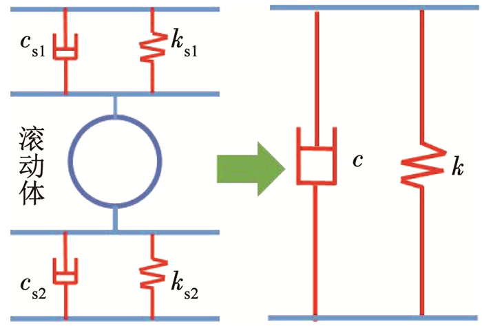
将滚动体与内滚道、外滚道接触的刚度和阻尼看作串联关系,如图 3所示,由复刚度方程式[18]得到总的刚度k和阻尼c为
| $ k+\mathrm{i} \omega c=\left(\frac{1}{k_{\mathrm{s} 1}+\mathrm{i} \omega c_{\mathrm{s} 1}}+\frac{1}{k_{\mathrm{s} 2}+\mathrm{i} \omega c_{\mathrm{s} 2}}\right)^{-1}. $ | (27) |
|
图 3 接触副刚度-阻尼模型 Fig. 3 Stiffness-damping model of contact coupling |
综上所述,考虑弹流润滑接触模型后的中介轴承力为
| $ \begin{array}{c} \begin{array}{*{20}{c}} {\left[ {\begin{array}{*{20}{c}} {{F_{{\rm{b}}y}}}\\ {{F_{{\rm{b}}z}}} \end{array}} \right] = k\sum\limits_{j = 1}^{{N_{\rm{b}}}} {{\lambda _j}} \left[ {\left( {{y_{\rm{i}}} - {y_{\rm{o}}}} \right)\cos {\theta _j} + } \right.}\\ {{{\left. {\left( {{z_{\rm{i}}} - {z_{\rm{o}}}} \right)\sin {\theta _j} - {\delta _0}} \right]}^{3/2}}\left[ {\begin{array}{*{20}{c}} {\cos {\theta _j}}\\ {\sin {\theta _j}} \end{array}} \right] + } \end{array}\\ c\sum\limits_{j = 1}^{{N_{\rm{b}}}} {{\lambda _j}} \left[ {\left( {{{\dot y}_{\rm{i}}} - {{\dot y}_{\rm{o}}}} \right)\cos {\theta _j} + \left( {{{\dot z}_{\rm{i}}} - {{\dot z}_{\rm{o}}}} \right)\sin {\theta _j}} \right]\left[ {\begin{array}{*{20}{c}} {\cos {\theta _j}}\\ {\sin {\theta _j}} \end{array}} \right]. \end{array} $ | (28) |
与不考虑弹流润滑作用的中介轴承力相比,考虑弹流润滑作用后改变了中介轴承接触刚度k并且增加了阻尼项.
1.4 系统方程无量纲化在系统动力学方程(1) 中引入量纲一的变换:
| $ \tau=\omega_{1} t, $ | (29) |
| $ \begin{array}{l} \mathit{\boldsymbol{P}} = {\left\{ {\begin{array}{*{20}{c}} {{Z_1}}&{{Z_2}}&{{Z_3}}&{{Z_4}}&{{Z_5}}&{{Y_1}}&{{Y_2}}&{{Y_3}}&{{Y_4}}&{{Y_5}} \end{array}} \right\}^{\rm{T}}} = \\ {\kern 1pt} {\kern 1pt} {\kern 1pt} {\kern 1pt} {\kern 1pt} {\kern 1pt} {\kern 1pt} {\kern 1pt} {\kern 1pt} {\kern 1pt} {\kern 1pt} {\kern 1pt} {\kern 1pt} {\kern 1pt} {\kern 1pt} {\kern 1pt} {\kern 1pt} {\kern 1pt} {\kern 1pt} {\kern 1pt} {\left\{ {\begin{array}{*{20}{l}} {\frac{{{z_1}}}{{{\delta _0}}}}&{\frac{{{z_2}}}{{{\delta _0}}}}&{\frac{{{z_3}}}{{{\delta _0}}}}&{\frac{{{z_4}}}{{{\delta _0}}}}&{\frac{{{z_5}}}{{{\delta _0}}}}&{\frac{{{y_1}}}{{{\delta _0}}}}&{\frac{{{y_2}}}{{{\delta _0}}}}&{\frac{{{y_3}}}{{{\delta _0}}}}&{\frac{{{y_4}}}{{{\delta _0}}}}&{\frac{{{y_5}}}{{{\delta _0}}}} \end{array}} \right\}^{\rm{T}}}, \end{array} $ | (30) |
| $ \mathit{\boldsymbol{\dot P}} = {\left\{ {\begin{array}{*{20}{c}} {\frac{{{{\dot z}_1}}}{{{\delta _0}{\omega _1}}}}& \cdots &{\frac{{{{\dot z}_5}}}{{{\delta _0}{\omega _1}}}}& \cdots &{\frac{{{{\dot y}_1}}}{{{\delta _0}{\omega _1}}}}& \cdots &{\frac{{{{\dot y}_5}}}{{{\delta _0}{\omega _1}}}} \end{array}} \right\}^{\rm{T}}}, $ | (31) |
| $ \mathit{\boldsymbol{\ddot P}} = {\left\{ {\begin{array}{*{20}{c}} {\frac{{{{\ddot z}_1}}}{{{\delta _0}{\omega _1}}}}& \cdots &{\frac{{{{\ddot z}_5}}}{{{\delta _0}{\omega _1}}}}& \cdots &{\frac{{{{\ddot y}_1}}}{{{\delta _0}{\omega _1}}}}& \cdots &{\frac{{{{\ddot y}_5}}}{{{\delta _0}{\omega _1}}}} \end{array}} \right\}^{\rm{T}}}, $ | (32) |
得系统量纲一的方程:
| $ \ddot{\boldsymbol{P}}+\boldsymbol{\xi} \dot{\boldsymbol{P}}+\boldsymbol{\kappa} \boldsymbol{P}=\boldsymbol{f}, $ | (33) |
其中:
| $ \boldsymbol{\xi}=\frac{1}{\omega_{1}} \boldsymbol{M}^{-1} \boldsymbol{C}, \boldsymbol{\kappa}=\frac{1}{\omega_{1}^{2}} \boldsymbol{M}^{-1} \boldsymbol{K}, \boldsymbol{f}=\frac{1}{\omega_{1}^{2}} \boldsymbol{M}^{-1} \boldsymbol{F}. $ |
式中:ξ为量纲一的阻尼矩阵;κ为量纲一的刚度矩阵;f为量纲一的力矢量.
1.5 系统参数选取设定高低压转子反向旋转,转速比λ固定,取λ=-1.3.取接触载荷Q为常数[19].由于非线性中介轴承力的存在,本文采用四阶变步长龙格-库塔法对方程(33)进行数值求解,系统计算参数[20]见表 1.
| 表 1 系统计算参数 Tab. 1 Parameters of the system |
为了解双转子系统的动力学特性,首先求解不考虑弹流润滑作用下系统的固有频率,即求解系统微分方程的特征值.选取z方向进行计算,系统频率方程:
| $ \left|\boldsymbol{K}_{z}-\omega_{0}^{2} \boldsymbol{M}_{c}\right|=0, $ | (34) |
其中:
| $ \boldsymbol{M}_{c}=\left[\begin{array}{ccccc} m_{1} & 0 & 0 & 0 & 0 \\ 0 & m_{2} & 0 & 0 & 0 \\ 0 & 0 & m_{3} & 0 & 0 \\ 0 & 0 & 0 & m_{4} & 0 \\ 0 & 0 & 0 & 0 & m_{5} \end{array}\right], $ |
| $ \boldsymbol{K}_{z}=\left[\begin{array}{ccccc} k_{1}+k_{5} & -k_{5} & 0 & 0 & 0 \\ -k_{5} & k_{5}+k_{6} & -k_{6} & 0 & 0 \\ 0 & -k_{6} & k_{6}+k_{7}+k_{\mathrm{b}} & -k_{7} & -k_{\mathrm{b}} \\ 0 & 0 & -k_{7} & k_{4}+k_{7} & 0 \\ 0 & 0 & -k_{\mathrm{b}} & 0 & k_{2}+k_{\mathrm{b}} \end{array}\right], $ |
式中kb为轴承线性化刚度,线性化方法详见文献[21].
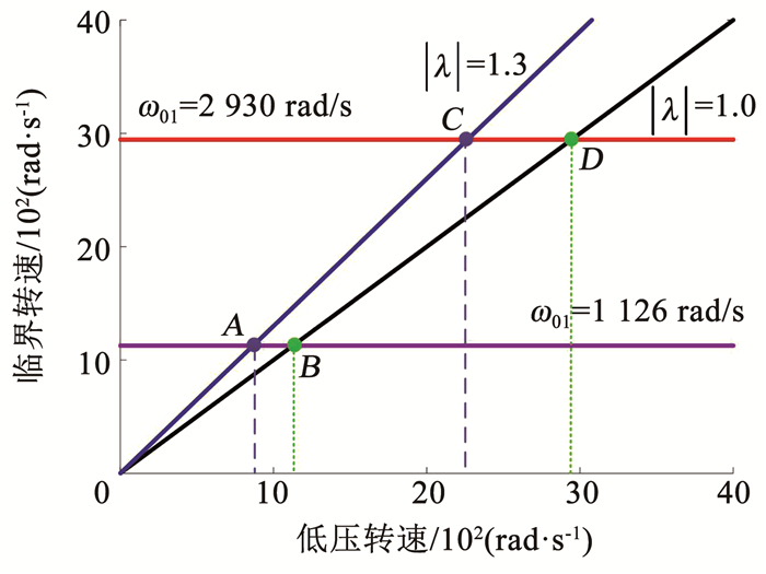
求得前两阶临界转速分别为ω01=1 126 rad/s、ω02=2 930 rad/s,系统坎贝尔图如图 4所示.一阶主共振A点ω1=866 rad/s由高压转子不平衡引起,一阶主共振B点ω1=1 126 rad/s由低压转子不平衡引起,二阶主共振C点ω1=2 254 rad/s由高压转子不平衡引起,二阶主共振D点ω1=2 930 rad/s由低压转子不平衡引起.由于高低压转子均存在不平衡激励,因此每一阶临界转速会出现两个共振峰.
|
图 4 系统坎贝尔图 Fig. 4 Campbell diagram of the system |
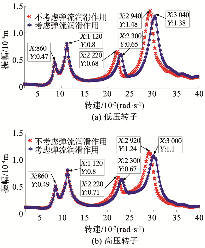
图 5为中介轴承-双转子系统的幅频响应曲线,采用ri和ro分别表示低压转子和高压转子的振幅.
| $ r_{\mathrm{i}}=\sqrt{y_{\mathrm{i}}^{2}+z_{\mathrm{i}}^{2}}, r_{\mathrm{o}}=\sqrt{y_{\mathrm{o}}^{2}+z_{\mathrm{o}}^{2}} \text { . } $ | (35) |
|
图 5 中介轴承-双转子系统幅频曲线 Fig. 5 Amplitude-frequency curves of intershaft bearing-dual rotor system |
当不考虑弹流润滑的影响时,低压转子的幅频响应曲线在转速860、1 120、2 220、2 940 rad/s处出现共振峰.与坎贝尔图得到的临界转速对应.转速860 rad/s处的第1个共振峰是高压转频激发的一阶共振,转速1 120 rad/s处的第2个共振峰是低压转频激发的一阶共振,转速2 220 rad/s处的第3个共振峰是高压转频激发的二阶共振,转速2 940 rad/s处的第4个共振峰是低压转频激发的二阶共振.高压转子与低压转子的响应有类似规律.
当考虑中介轴承弹流润滑作用的影响后,低压转子和高压转子响应一阶共振峰无明显变化,但二阶共振峰均向右移动,并且在共振峰处振幅减小.低压转子和高压转子的响应规律一致.
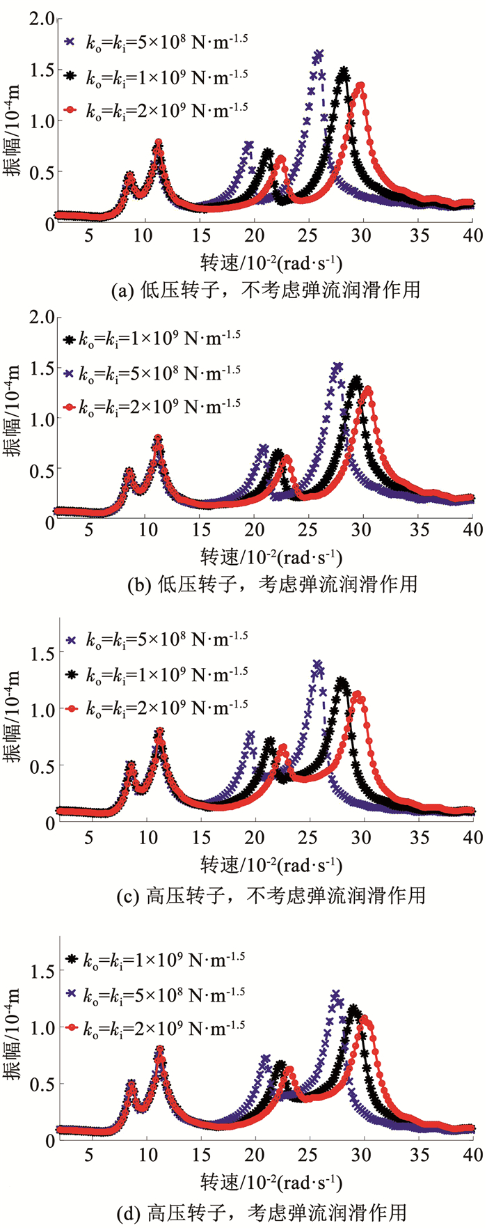
2.2 中介轴承赫兹接触刚度对系统特性的影响研究中介轴承弹流润滑作用下,中介轴承赫兹接触刚度变化对低压转子和高压转子幅频响应的影响.图 6为中介轴承赫兹接触刚度分别为1×10⁹、5×10⁸、2×10⁹ N·m-1.5时,低压转子和高压转子的幅频响应曲线.从幅频曲线来看,赫兹接触刚度增大,一阶共振峰无明显变化,二阶共振峰向右移动且共振峰幅值减小,低压转子和高压转子响应规律一致.表 2、3分别给出了低压转子和高压转子在不同中介轴承赫兹接触刚度的情况下,考虑弹流润滑作用与不考虑弹流润滑作用相比,振动幅值的相对改变量.在一阶共振峰处,振幅改变小于5%,由于转速较低时系统整体振幅较小,因此幅频曲线无明显变化.在二阶共振峰处振幅改变较明显,相对改变量在4%~8%之间.低压转子和高压转子的一阶共振峰位置均未发生偏移,而二阶共振峰向高频移动2%~7%,见表 4、5.
|
图 6 不同赫兹接触刚度时双转子系统幅频曲线 Fig. 6 Amplitude-frequency curves of dual rotor system with different Hertz contact stiffness |
| 表 2 低压转子振动幅值相对改变量 Tab. 2 Relative changes in vibration amplitude of low pressure rotor |
| 表 3 高压转子振动幅值相对改变量 Tab. 3 Relative changes in vibration amplitude of high pressure rotor |
| 表 4 低压转子共振峰位置对应的转速相对改变量 Tab. 4 Relative changes in the speed corresponding to the resonant peak of low pressure rotor |
| 表 5 高压转子共振峰位置对应的转速相对改变量 Tab. 5 Relative changes in the speed corresponding to the resonant peak of high pressure rotor |
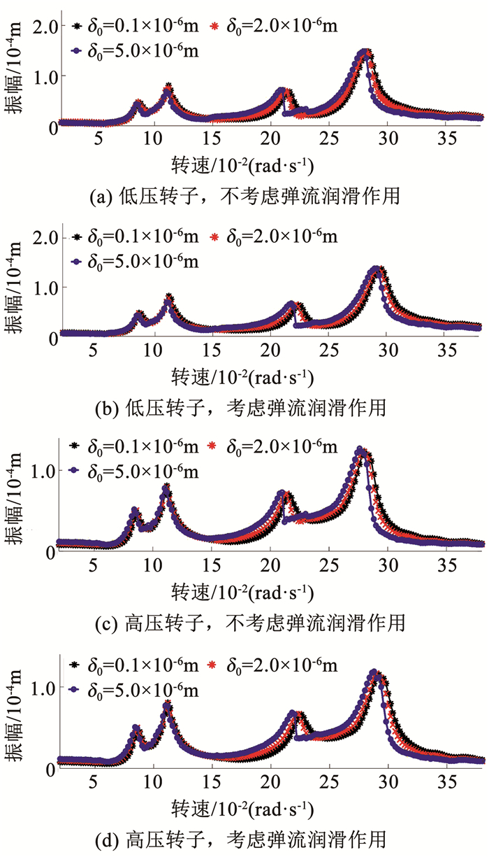
考虑中介轴承弹流润滑的条件下,分析中介轴承径向游隙变化对低压转子和高压转子幅频响应的影响.图 7为径向游隙分别为δ0=0.1×10⁻⁶ m,δ0=2.0×10⁻⁶ m和δ0=5.0×10⁻⁶ m情况下,低压转子和高压转子的幅频响应曲线.随着径向游隙增大,一阶共振峰无明显变化,二阶共振峰沿转速轴向左移动,并且中介轴承非线性特性在高压转子和低压转子的幅频响应中表现明显.
|
图 7 不同径向游隙时双转子系统幅频曲线 Fig. 7 Amplitude-frequency curves of dual rotor system with different radical clearances |
表 6、7分别给出了低压转子和高压转子在不同中介轴承径向游隙的情况下,考虑弹流润滑作用与不考虑弹流润滑作用相比,振动幅值的相对改变量.
| 表 6 低压转子振动幅值相对改变量 Tab. 6 Relative changes in vibration amplitude of low pressure rotor |
| 表 7 高压转子振动幅值相对改变量 Tab. 7 Relative changes in vibration amplitude of high pressure rotor |
在一阶共振峰处,振幅改变小于4%,在二阶共振峰处振幅改变较明显,相对改变量在4%~9%之间.低压转子和高压转子一阶共振峰位置对应的转速未发生改变,而二阶共振峰位置对应的转速改变2%~8%,见表 8、9.
| 表 8 低压转子共振峰位置对应的转速相对改变量 Tab. 8 Relative changes in the speed corresponding to the resonant peak of low pressure rotor |
| 表 9 高压转子共振峰位置对应的转速相对改变量 Tab. 9 Relative changes in the speed corresponding to the resonant peak of high pressure rotor |
在润滑油黏度范围0.002~0.400 Pa·s内,分别取润滑油黏度为0.003、0.030、0.300 Pa·s,计算一阶和二阶共振峰处低压转子和高压转子的振动幅值,以及考虑弹流润滑作用后转子振动幅值的相对改变量,见表 10、11.
| 表 10 低压转子振动幅值及振幅相对改变量 Tab. 10 Vibration amplitude and its relative change for low pressure rotor |
| 表 11 高压转子振动幅值及振幅相对改变量 Tab. 11 Vibration amplitude and its relative change for high pressure rotor |
从表中可看出,考虑弹流润滑作用的影响后,一阶共振峰处振动幅值相对改变量较小,二阶共振峰处振动幅值相对改变量较大.不同润滑剂黏度对高低压转子振动幅值影响小于1%.并且润滑剂黏度越高,低压转子和高压转子的振动幅值越小.这是由于润滑剂黏度越高,其阻尼作用越大,因此减振效果越好.此结论与文献[22]中利用实验方法研究润滑油黏度对轴承振动影响的结论一致.
3 实验研究利用双转子振动特性实验台对比研究考虑中介轴承弹流润滑作用和不考虑中介轴承弹流润滑作用时双转子系统的动力学特性.
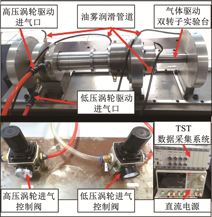
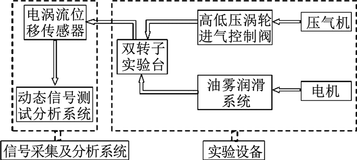
3.1 实验装置实验装置如图 8所示,主要包括气体驱动双转子实验台、空气压缩机、高低压涡轮进气控制阀、油雾润滑系统、TST数据采集系统、直流电源、前置器、电涡流传感器、计算机、TST动态测试分析软件.
|
图 8 实验装置 Fig. 8 Experimental facility |
气体驱动双转子实验台是根据某型航空发动机的整机结构简化而来的,包括低压转子、高压转子以及中介轴承等支承结构[23].为了最大限度地接近真实工况,高压转子和低压转子均通过气体驱动涡轮旋转进而带动转子结构旋转,高低压转子反向旋转,转速比可随意设定,此处控制高低压转子转速比为-1.3.并且实验台是可拆装的,可以更换中介轴承.
空气压缩机为双转子实验台提供动力;高低压涡轮进气控制阀可控制进气量,进而控制高低压转子的转速;油雾润滑系统提供润滑和冷却作用;直流电源和前置器配合使用,为电涡流传感器提供交变电流;TST数据采集系统、TST动态测试分析软件和计算机可对传感器的输出信号进行记录、显示和分析.实验系统框图如图 9所示.
|
图 9 实验系统框图 Fig. 9 Block diagram of experimental system |
在中介轴承两种不同工况下,分别进行双转子系统振动实验.1)洗净中介轴承润滑油,并关闭油雾润滑系统;2)中介轴承充分润滑,并打开油雾润滑系统.
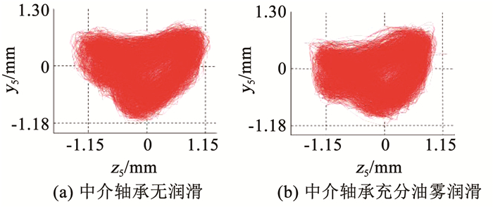
图 10为低压转子转速314 rad/s,高低压转速比为-1.3的工况下,高压转子的轴心轨迹图.对比图 10(a)、10(b)可以发现在中介轴承充分润滑的工况下,转子轴心轨迹的范围更小,即转子系统的振动减小.
|
图 10 高压转子轴心轨迹 Fig. 10 Whirling orbit of high pressure rotor |
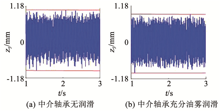
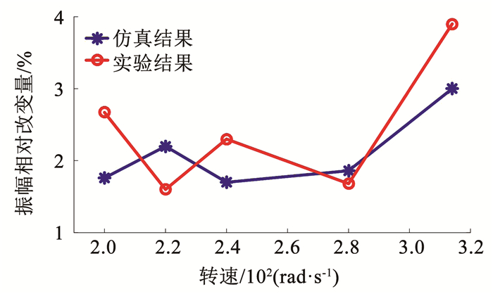
图 11为中介轴承考虑润滑和不考虑润滑两种工况下高压转子的时间历程图,可明显看出中介轴承充分油雾润滑的情况下,转子振动幅值减小,振动幅值相对改变量为3.90%.图 12为与实验相同工况下的仿真结果,考虑弹流润滑作用后振动幅值减小3%.图 13对比了仿真和实验条件下,转速200、220、240、280、314 rad/s时,考虑弹流润滑作用后高压转子振动幅值的相对改变量,在实验转速范围内,转子振幅相对改变量小于4%.低压转子和高压转子通过中介轴承耦合,低压转子有类似规律,此处不再赘述.可见实验与仿真得到的转子振幅相对改变量具有一致性,因此实验结果可靠,进而能够验证仿真结果是合理的.
|
图 11 实验结果 Fig. 11 Experimental results |

|
图 12 仿真结果 Fig. 12 Simulation results |
|
图 13 振幅变化百分数 Fig. 13 Change percentage of vibration amplitude |
由于实验台结构复杂,临界转速高等各种实验条件的限制,以及目前对考虑润滑的中介轴承-双转子系统实验探究的文献较少,研究还有待深入,因此本实验中主要研究了考虑中介轴承弹流润滑作用后双转子系统振动幅值的变化规律.
4 结论1) 从幅频曲线来看,弹流润滑作用对一阶共振峰附近高低压转子的振幅及共振峰位置影响较小,对高转速区间的共振峰影响较大,使系统共振峰右移并且共振峰处振幅减小.低压转子和高压转子的响应规律一致.
2) 分别改变中介轴承赫兹接触刚度和径向游隙,考虑弹流润滑作用与不考虑弹流润滑作用相比,一阶共振峰处振幅改变小于5%,由于转速较低时系统整体振幅较小,幅频曲线无明显变化.在二阶共振峰处振幅改变较明显,改变百分数在4%~9%之间.一阶共振峰位置未发生偏移,二阶共振峰向高频移动2%~8%.改变润滑油黏度,对低压转子和高压转子振动幅值影响小于1%.
3) 实验结果与仿真结果进行对比,在实验转速区间内,考虑中介轴承弹流润滑作用时系统振动幅值相对改变量小于4%,仿真和实验具有一致性.因此随着加工误差、工艺缺陷的降低以及数值计算精度的提高,为准确描述双转子系统的动力学特性,应考虑中介轴承弹流润滑作用的影响.
| [1] |
FERRARIS G, MAISONNEUVE V, LALANNE M. Prediction of the dynamic behavior of non-symmetrical coaxial co-or counter-rotating rotors[J]. Journal of Sound and Vibration, 1996, 195(4): 649. DOI:10.1006/jsvi.1996.0452 |
| [2] |
CHEN Guo. Vibration modelling and verifications for whole aero-engine[J]. Journal of Sound and Vibration, 2015, 349: 163. DOI:10.1016/j.jsv.2015.03.029 |
| [3] |
HU Qinghua, DENG Sier, TENG Hongfei. A 5-DOF model for aeroengine spindle dual-rotor system analysis[J]. Chinese Journal of Aeronautics, 2011, 24(2): 224. DOI:10.1016/S1000-9361(11)60027-7 |
| [4] |
白雪川. 航空发动机反向旋转双转子系统动力学特性研究[D]. 天津: 天津大学, 2013 BAI Xuechuan. Research on dynamical characteristics of counter-rotating dual-rotor system of aero-engines[D]. Tianjing: Tianjin University, 2013 |
| [5] |
张天程, 曹树谦, 李利青, 等. 碰摩双转子系统弯扭耦合振动分析与实验[J]. 航空动力学报, 2019, 34(3): 643. ZHANG Tiancheng, CAO Shuqian, LI Liqing, et al. Analysis and experiment of coupled bending and torsional vibration of a rub-impact dual-rotor system[J]. Journal of Aerospace Power, 2019, 34(3): 643. DOI:10.13224/j.cnki.jasp.2019.03.016 |
| [6] |
WANG Nanfei, JIANG Dongxiang, XU Hongzhi. Dynamic characteristics analysis of a dual-rotor system with inter-shaft bearing[J]. Proceedings of the Institution of Mechanical Engineers Part G: Journal of Aerospace Engineering, 2017, 233(3): 1147. DOI:10.1177/0954410017748969 |
| [7] |
GAO Peng, HOU Lei, YANG Rui, et al. Local defect modelling and nonlinear dynamic analysis for the inter-shaft bearing in a dual-rotor system[J]. Applied mathematical Modeling, 2019, 68: 29. DOI:10.1016/j.apm.2018.11.014 |
| [8] |
SUN Chuanzong, CHEN Yushu, HOU Lei. Steady-state response characteristics of a dual-rotor system induced by rub-impact[J]. Nonlinear Dynamics, 2016, 86(1): 91. DOI:10.1007/s11071-016-2874-2 |
| [9] |
HOU Lei, CHEN Yushu, FU Yiqiang, et al. Application of the HB-AFT method to the primary resonance analysis of a dual-rotor system[J]. Nonlinear Dynamics, 2017, 88(4): 2531. DOI:10.1007/s11071-17-03394-4 |
| [10] |
赵联春. 球轴承振动的研究[D]. 杭州: 浙江大学, 2003 ZHAO Lianchun. Research on vibration of ball bearings[D]. Hangzhou: Zhejiang University, 2003 |
| [11] |
张彤, 王占彬, 王晓力. 弹流润滑球轴承-转子系统非线性动力学分析[J]. 北京理工大学学报, 2012, 32(3): 244. ZHANG Tong, WANG Zhanbin, WANG Xiaoli. Analysis of the nonlinear dynamic behaviors of a rotor-ball bearing system with elasto-hydrodynamic lubrication[J]. Transactions of Beijing Institute of Technology, 2012, 32(3): 244. |
| [12] |
张俊红, 马梁, 马文朋, 等. 基于弹流润滑转子-滚动轴承系统碰摩-不对中耦合故障的动力学分析[J]. 航空动力学报, 2014, 29(8): 1940. ZHANG Junhong, MA Liang, MA Wenpeng, et al. Dynamic analysis of rotor-ball bearing system based on elasto-hydrodynamic lubrication with rubbing-misalignment coupling fault[J]. Journal of Aerospace Power, 2014, 29(8): 1940. DOI:10.13224/j.cnki.jasp.2014.08.023 |
| [13] |
王占彬, 王晓力. 弹流润滑球轴承-转子系统载荷特性分析[J]. 机械设计与制造, 2016(12): 35. WANG Zhanbin, WANG Xiaoli. Analysis of the load behavior of a rotor-ball bearing with elasto-hydrodynamic lubrication[J]. Machinery Design and Manufacture, 2016(12): 35. DOI:10.19356/j.cnki.1001-3997.2016.12.010 |
| [14] |
田晶, 艾延廷, 赵明, 等. 考虑弹流润滑影响的表面局部缺陷中介轴承动力学建模[J]. 振动与冲击, 2019, 38(5): 80. TIAN Jing, AI Yanting, ZHAO Ming, et al. Dynamic modeling for inter-shaft bearing with surface local defect considering elasto-hydro lubrication effects[J]. Journal of Vibration and Shock, 2019, 38(5): 80. DOI:10.13465/j.cnki.jvs.2019.05.011 |
| [15] |
张智勇. 球轴承—转子系统变柔度振动的分岔与滞后行为[D]. 哈尔滨: 哈尔滨工业大学, 2015 ZHANG Zhiyong. Bifurcations and hysteresis of varying compliance vibrations of a ball bearing-rotor system[D]. Harbin: Harbin Institute of Technology 2015 |
| [16] |
剡昌锋, 苑浩, 王鑫, 等. 点接触弹流润滑条件下的深沟球轴承表面局部缺陷动力学建模[J]. 振动与冲击, 2016, 35(14): 61. YAN Changfeng, YUAN Hao, WANG Xin, et al. Dynamics modeling on local defect of deep groove ball bearing under point contact elasto-hydrodynamic lubrication condition[J]. Journal of Vibration and Shock, 2016, 35(14): 61. DOI:10.13465/j.cnki.jvs.2016.14.010 |
| [17] |
杨洋. 碰摩力模型研究及其在转子—机匣系统中的应用[D]. 哈尔滨: 哈尔滨工业大学, 2016 YANG Yang. Investigation of rub-impact force model and its applications in rotor-casing system[D]. Harbin: Harbin Institute of Technology, 2016 |
| [18] |
SARANGI M, MAJUMDAR B C, SAKHAR A S. Stiffness and damping characteristics of lubricated ball bearing considering the surface roughness effect, part I: Theoretical formulation[J]. Proceedings of the Institution of Mechanical Engineers, Part J: Journal of Engineering Tribology, 2004, 218(6): 529. DOI:10.1243/1350650042794716 |
| [19] |
ZHANG Yuyan, WANG Xiaoli, YAN Xiaoliang. Dynamic behaviors of the elastohydrodynamic lubricated contact for rolling bearings[J]. Journal of Tribology, 2013, 135(2): 021501. DOI:10.1115/1.4023084 |
| [20] |
温诗铸, 黄平. 摩擦学原理[M]. 第4版. 北京: 清华大学出版社, 2012. WEN Shizhu, HUANG Ping. Principles of tribology[M]. 4th ed. Beijing: Tsinghua University Press, 2012. |
| [21] |
路振勇, 侯磊, 孙传宗, 等. 六点支承航空发动机双转子系统动力学离散模型[J]. 中国科学: 技术科学, 2016, 46(11): 1185. LU Zhenyong, HOU Lei, SUN Chuanzong, et al. Discrete dynamical model for the dual-rotor systems with six supports of the aero-engine[J]. Scientia Sinica: Technologica, 2016, 46(11): 1185. DOI:10.1360/N092016-00084 |
| [22] |
李秀香. 润滑油黏度对轴承振动的影响[J]. 轴承, 1992(2): 39. LI Xiuxiang. Influence of lubricating oil viscosity on bearing vibration[J]. Bearing, 1992(2): 39. DOI:10.19533/j.issn1000-3762.1992.02.018 |
| [23] |
HOU Lanlan, CAO Shuqian, GAO Tian, et al. Vibration signal model of an aero-engine rotor-casing system with a transfer path effect and rubbing[J]. Measurement, 2019, 141: 429. DOI:10.1016/j.measurement.2019.02.049 |
 2021, Vol. 53


