2. 高效洁净机械制造教育部重点实验室(山东大学) 济南 250061;
3. 山东大学 控制科学与工程学院,济南 250061;
4. 智能无人系统教育部工程研究中心(山东大学)济南 250061
2. Key Laboratory of High-Efficiency and Clean Mechanical Manufacture, Ministry of Education (Shandong University), Jinan 250061, China;
3. School of Control Science and Engineering, Shandong University, Jinan 250061, China;
4. Engineering Research Center of Intelligent Unmanned System, Ministry of Education (Shandong University), Jinan 250061, China
随着机器人技术与微创手术的愈发成熟,代表着微创手术顶尖技术的微创手术机器人应运而生[1]。主从式微创手术机器人的出现提高了微创手术的精度与可靠性,医生通过主操作手对手术器械进行遥操作,数字化的机械手代替人手完成手术,可减小手部颤动带来的影响,从而使手术动作更加灵活、准确。近年来,随着对连续体机械臂[2-3]和力反馈技术[4]的深入研究,进一步扩大了微创手术机器人的应用场景,同时也对主操作手性能提出了更高的要求。主操作手在保证具有足够工作空间的基础上,应具备良好的运动性能,以确保主从控制和力反馈的准确性,从而进一步提高手术的成功率以及降低医生在进行手术操作时的疲劳感[5]。
主操作手可分为串联型和并联型两个类别,分别以Touch系列[6-7]和Sigma[8]系列为代表,但这两种通用型主操作手价格十分昂贵,且对微创手术并不具针对性,所以在国内外多个团队的手术机器人系统中,大多使用专门设计的主操作手。串联型主操作手结构简单,且具备较大工作空间和良好的运动性能,目前在医疗领域多采用串联型结构。da Vinci Surgical System[9-10]中所设计的主操作手,具备较大工作空间,能够提供六维力反馈,但其操作端整体机构过于庞大,且位姿具有耦合关系;英国帝国理工学院Wisanuvej等[11]和韩国科学技术院Lee等[12]设计的主操作手为主从间各关节一一映射的近似同构关系,这种主从同构设计可以提高医生操作时的直观性和透明性,但同时也存在应用领域较为狭窄和位姿耦合的问题;哈尔滨工业大学王涛等[13-14]基于串联结构设计了一种7自由度主操作手,具备较大工作空间和主动重力补偿能力,Liang等[15]基于平行四边形机构和位置补偿机构,设计了一种位姿完全解耦的9关节主操作手,具备六维力反馈功能和良好的运动性能,但其在位置补偿机构中新加入了一个电机用于实现位姿解耦,略微增加了控制系统的复杂性;天津大学王树新等[16-17]在其“妙手”微创手术机器人系统中设计了一种绳驱动6自由度主操作手,具有体积小、重量轻以及工作空间内无奇异点等特点;天津工业大学桑宏强等[18]设计了一种具备位置高精度的串联型主操作手,但未在位姿耦合方面进行研究。
目前,国内外在主操作手方面的研究大多未考虑位姿耦合的问题,而现有的少数解耦策略会增加控制系统的复杂性。因此设计一种基于机械结构的位姿解耦主操作手,对提高医生在进行操作时的直观性和稳定性有重要意义。为此,设计了一种多节串联型主操作手,该主操作手在保留经典串联结构优点的基础上,只通过机械结构实现了位姿进一步解耦,并未增加控制难度;分析了主操作手的正、逆运动学,从运动学和几何角度验证了位姿解耦策略的正确性;求解了主操作手的雅可比矩阵,分析了基于雅可比矩阵的多种运动性能评价指标,并定义了一种综合运动性能评价指标,采用遗传算法对该指标进行了优化分析,以确保主操作手在位姿解耦的基础上,仍具备良好且平稳的运动性能。
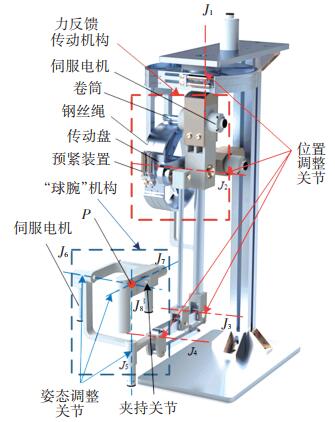
1 主操作手结构设计为满足对手术器械末端点在空间中任意位置和姿态的控制,所设计的主操作手共有8个关节,6个自由度,采用串联型结构,整体可细分为3部分:1)位置调整机构,包括3个自由度,由4个旋转关节组成,用于控制手术器械末端点在空间中的位置;2)姿态调整机构,包括3个自由度,由3个旋转关节组成,用于控制手术器械末端点在空间中的姿态;3)夹持机构由1个开合关节构成,用于控制手术器械的开合运动,整体机构如图 1所示。
|
图 1 主手整体结构 Fig. 1 Overall structure of master manipulator |
位置调整机构由3个主动关节J1、J2、J3和1个被动关节J4组成。主动关节为装配有Maxon直流伺服电机和编码器的独立关节。编码器用于检测关节转动角度,并结合正运动学,实现主从控制;电机则通过输出力矩,实现重力平衡和力反馈。力反馈传动机构如图 1红色虚线框内所示,主动关节所配备的直流伺服电机通过固定于电机轴上的卷筒和钢丝绳与传动盘构成绳传动减速机构,以此达到增加输出转矩,实现力反馈功能的目的。
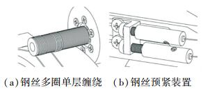
为了提高绳传动的传动能力,采用有螺旋导槽的多圈单层缠绕方式,如图 2(a)所示。这种卷绕方式通过增加缠绕圈数不仅提高了传动扭矩,而且可以降低传动误差[19],同时因为导槽的存在,可避免钢丝相互摩擦,增加了钢丝与卷筒的接触面积,降低了相应的接触应力,使钢丝具有较长使用寿命[20]。钢丝绳的预紧力对绳传动的传动精度有较大影响,设计如图 2(b)所示预紧装置,可方便快速地对钢丝绳预紧力进行调节。
|
图 2 钢丝绳传动机构 Fig. 2 Wire rope transmission mechanism |
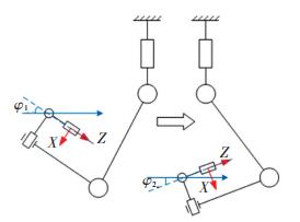
在图 3所示结构中,坐标系表示主操作手末端点的姿态。当姿态调整机构各关节角度保持不变,主操作手进行位置调整时,坐标系发生了转动,说明其姿态与位置具有耦合关系。这就意味着当医生对主操作手在空间中的不同位置,进行相同姿态的操作时,例如使末端姿态保持水平,关节之间具有不同的角度关系φ1、φ2,导致操作不具备一致性,影响了医生操作的舒适感。设计被动关节的目的在于解除姿态与位置的耦合关系。
|
图 3 位姿耦合关系 Fig. 3 Position and posture coupling relationship |
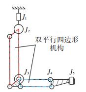
通过引入双平行四边形机构在位置调整机构与姿态调整机构中间添加了一个被动关节J4,如图 4所示,该关节无独立电机、编码器配置,不具备主动运动能力。J4随着J2、J3的转动而转动,抵消了这两个关节转动对末端姿态的影响,具体在下文正运动学部分进行说明。通过该被动关节可使姿态调整机构的初始位置始终保持水平,提高了操作的一致性和直觉感。引入的平行四杆机构也在一定程度提高了主操作手的刚度,而且该设计也有助于简化主操作手的运动学建模的计算量。
|
图 4 双平行四边形机构 Fig. 4 Double parallelogram mechanism |
姿态调整机构采用了经典的机器人“球腕”机构,即关节J5、J6和J7这3个轴的轴线相交于一点P,如图 1蓝色虚线框内所示。这种设计可使主操作手末端点的位置不受这3个关节转动的影响,同时有助于逆运动学的求解,具体在本文运动学部分对此进行说明。姿态调整机构中的3个关节同样各自配备独立的Maxon直流伺服电机与编码器,用于实现重力平衡、力反馈与主手位姿求解。夹持机构主要用于控制从操作手末端手术器械的夹持、剪切等操作,以及反馈器械与组织之间的接触力,主体结构由开合关节、手柄、电机和绳传动减速机构构成。
2 主操作手运动学分析在微创手术机器人系统中,为实现医生通过主操作手控制从端手术器械运动,需要主操作手末端坐标与从操作手末端坐标之间建立一定映射关系。因此,需要通过主手各关节角度解算主操作手的正向运动学,来获取主操作手末端的位置与姿态信息。同时,主操作手也应具备根据从操作手的位姿主动调节自身位姿的能力,因此也需解算主手逆向运动学。
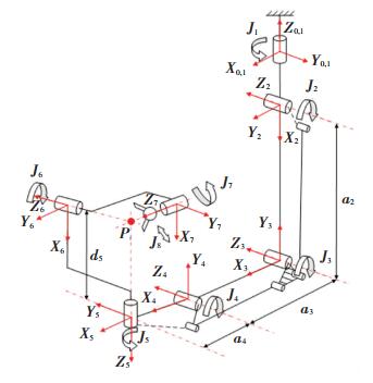
2.1 正运动学分析主操作手正运动学是在各连杆几何特征已知的前提下,通过测量各个关节转角,来求解主操作手末端的位姿。主操作手的各关节角度由编码器测得,采用改进后的D-H(Denavit-Hartenberg)参数法进行分析,主操作手运动学模型的建立如图 5所示,D-H参数如表 1所示。由于夹持机构中的关节J8与主操作手运动无关,故在运动学分析中将其忽略。
|
图 5 主操作手运动学模型 Fig. 5 Kinematics model of master manipulator |
| 表 1 主操作手D-H参数表 Tab. 1 D-H parameters of master manipulator |
将D-H参数表中相应数据代入式(1),得到各个关节的旋转变换矩阵:
| $ \begin{array}{l} {_{i}^{i-1}} \boldsymbol{T}= \\ {\left[\begin{array}{cccc} \cos \theta_{i} & -\sin \theta_{i} & 0 & a_{i-1} \\ \sin \theta_{i} \cos \alpha_{i-1} & \cos \theta_{i} \cos \alpha_{i-1} & -\sin \alpha_{i-1} & -\sin \alpha_{i-1} d_{i} \\ \sin \theta_{i} \sin \alpha_{i-1} & \cos \theta_{i} \sin \alpha_{i-1} & \cos \alpha_{i-1} & \cos \alpha_{i-1} d_{i} \\ 0 & 0 & 0 & 1 \end{array}\right]} \end{array} $ | (1) |
再将各关节的旋转变换矩阵进行矩阵连乘,即可得到主操作手位姿矩阵:
| $ { }_{7}^{0} \boldsymbol{T}={ }_{1}^{0} \boldsymbol{T}_{2}^{1} \boldsymbol{T} \cdots{ }_{7}^{6} \boldsymbol{T}=\left[\begin{array}{ll} \boldsymbol{R} & \boldsymbol{P} \\ 0 & 1 \end{array}\right]=\left[\begin{array}{cccc} r_{11} & r_{12} & r_{13} & p_{x} \\ r_{21} & r_{22} & r_{23} & p_{y} \\ r_{31} & r_{32} & r_{33} & p_{z} \\ 0 & 0 & 0 & 1 \end{array}\right] $ | (2) |
式中:位姿矩阵70Τ的子矩阵R表示主手末端在操作空间中的姿态,子矩阵P表示主手末端在操作空间中的位置,s θi和c θi分别表示sin θi和cos θi,矩阵各元素具体值如式(3)所示:
| $ \left\{\begin{aligned} r_{11}=& \mathrm{c} \theta_{5} \mathrm{s} \theta_{1} \mathrm{s} \theta_{7}-\mathrm{c} \theta_{1} \mathrm{s} \theta_{5} \mathrm{s} \theta_{7}+\mathrm{c} \theta_{1} \mathrm{c} \theta_{5} \mathrm{c} \theta_{6} \mathrm{c} \theta_{7}+\\ & \mathrm{c} \theta_{6} \mathrm{c} \theta_{7} \mathrm{s} \theta_{1} \mathrm{s} \theta_{5} \\ r_{21}=& \mathrm{c} \theta_{5} \mathrm{c} \theta_{6} \mathrm{c} \theta_{7} \mathrm{s} \theta_{1}-\mathrm{c} \theta_{1} \mathrm{c} \theta_{5} \mathrm{s} \theta_{7}-\mathrm{c} \theta_{1} \mathrm{c} \theta_{6} \mathrm{c} \theta_{7} \mathrm{s} \theta_{5}-\\ & \mathrm{s} \theta_{1} \mathrm{s} \theta_{5} \mathrm{s} \theta_{7} \\ r_{31}=& \mathrm{c} \theta_{7} \mathrm{s} \theta_{6} \\ r_{12}=& \mathrm{c} \theta_{5} \mathrm{c} \theta_{7} \mathrm{s} \theta_{1}-\mathrm{c} \theta_{1} \mathrm{c} \theta_{7} \mathrm{s} \theta_{5}-\mathrm{c} \theta_{1} \mathrm{c} \theta_{5} \mathrm{c} \theta_{6} \mathrm{s} \theta_{7}-\\ & \mathrm{c} \theta_{6} \mathrm{s} \theta_{1} \mathrm{s} \theta_{5} \mathrm{s} \theta_{7} \\ r_{22}=& \mathrm{c} \theta_{1} \mathrm{c} \theta_{6} \mathrm{s} \theta_{5} \mathrm{s} \theta_{7}-\mathrm{c} \theta_{1} \mathrm{c} \theta_{5} \mathrm{s} \theta_{7}-\mathrm{c} \theta_{7} \mathrm{s} \theta_{1} \mathrm{s} \theta_{5}-\\ & \mathrm{c} \theta_{5} \mathrm{c} \theta_{6} \mathrm{s} \theta_{1} \mathrm{s} \theta_{7} \\ r_{32}=&-\mathrm{s} \theta_{6} \mathrm{s} \theta_{7} \\ r_{13}=& \mathrm{c}\left(\theta_{1}-\theta_{5}\right) \mathrm{s} \theta_{6} \\ r_{23}=& \mathrm{s}\left(\theta_{1}-\theta_{5}\right) \mathrm{s} \theta_{6} \\ r_{33}=&-\mathrm{c} \theta_{6} \\ p_{x}=& \mathrm{c} \theta_{1}\left[a_{4}+a_{3} \mathrm{c}\left(\theta_{2}+\theta_{3}\right)+a_{2} \mathrm{c} \theta_{2}\right] \\ p_{y}=& \mathrm{s} \theta_{1}\left[a_{4}+a_{3} \mathrm{c}\left(\theta_{2}+\theta_{3}\right)+a_{2} \mathrm{c} \theta_{2}\right] \\ p_{z}=& a_{3} \mathrm{s}\left(\theta_{2}+\theta_{3}\right)-d_{5}+a_{2} \mathrm{s} \theta_{2} \end{aligned}\right. $ | (3) |
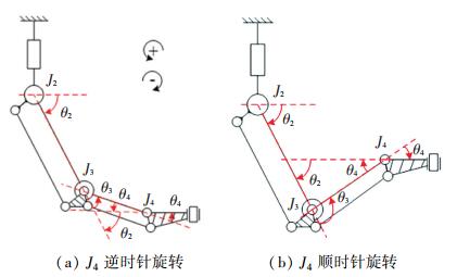
分析式(3)中各元素可知,主操作手末端点位置在“球腕”机构的作用下,位置向量P只受前3个关节角度影响。姿态矩阵R只包含θ1、θ5、θ6和θ7这4个角度信息,说明其姿态变换只与这4个角度有关。相比于其他串联型主操作手位姿分离设计[21-22],(末端姿态至少与6个关节角度相关,处于完全耦合状态),解除了姿态与位置中两个关节的耦合关系。这得益于引入的平行四杆机构所产生的被动关节J4。当医生对主1手进行操作,关节J2与J3发生角度变化时,J4会产生相应的负角度变化,原理如图 6所示。
|
图 6 主操作手解耦原理 Fig. 6 Decoupling principle of master manipulator |
根据D-H参数法定义,图 6中各关节逆时针旋转时,对应的关节角θ为正,顺时针时为负,且由表 1可知,在工作空间内θ2始终为负,θ3始终为正。θ4与θ2和θ3的线性关系,可分为正负两种情况,由几何关系不难得出两种情况的角度关系分别为|θ4|+|θ3|=|θ2|和|θ4|+|θ2|=|θ3|。按照规定分别代入θ2、θ3和θ4的符号后可求得θ4+θ3=-θ2和-θ4-θ2=θ3,即
| $ \theta_{4}=-\theta_{2}-\theta_{3} $ | (4) |
这种负角度变化可以抵消J2和J3角度变化对姿态部分带来的影响,以此实现位姿进一步解耦。同时通过与文献[21-22]对比分析可知,该结构可以降低主操作手正逆运动学的求解难度。
2.2 逆运动学分析为实现力反馈功能,在主手的各个关节均装一个有直流伺服电机,使主手在实现力反馈功能的基础上,同时具备了主动运动的能力。逆运动学是根据主手末端点在操作空间下的位姿,求解出各个关节对应的角度。利用电机驱动和逆运动学,能够实现主操作手根据从操作手位姿进行主动调节的功能。
因为在姿态部分采用了机器人“球腕”位姿分离设计,满足机器人Pieper准则,因此可采用逆变换代数方法求得主手的封闭解。在式(2)两侧同乘10T-1后得10Τ-1 70T=71T,取出等式两端矩阵中对应的位置元素,可得:
| $ \left\{\begin{array}{l} \mathrm{c} \theta_{1} p_{x}+\mathrm{s} \theta_{1} p_{y}=a_{4}+a_{3} \mathrm{c}\left(\theta_{2}+\theta_{3}\right)+a_{2} \mathrm{c} \theta_{2} \\ -\mathrm{s} \theta_{1} p_{x}+\mathrm{c} \theta_{1} p_{y}=0 \\ p_{z}=-d_{5}+a_{3} \mathrm{s}\left(\theta_{2}+\theta_{3}\right)+a_{2} \mathrm{s} \theta_{2} \end{array}\right. $ | (5) |
根据式(5)第二项,利用三角代换可得:
| $ \theta_{1}=\arctan \left(p_{y} / p_{x}\right), \theta_{1} \in\left[-80^{\circ}, 80^{\circ}\right] $ | (6) |
将式(5)两端平方后,相加消元后可求得:
| $ \begin{array}{l} \theta_{3}=\arctan \left[\pm\left[\left(2 a_{2} a_{3}\right)^{2}-\left[\left(\mathrm{c} \theta_{1} p_{x}+\mathrm{s} \theta_{1} p_{y}-a_{4}\right)^{2}+\right.\right.\right.\\ \left.\left.\left(p_{z}+d_{5}\right)^{2}-a_{2}^{2}-a_{3}^{2}\right]^{1 / 2}\right] /\left[\left(\mathrm{c} \theta_{1} p_{x}+\mathrm{s} \theta_{1} p_{y}-a_{4}\right)^{2}+\right.\\ \left.\left.\left(p_{z}+d_{5}\right)^{2}-a_{2}^{2}-a_{3}^{2}\right]\right], \theta_{3} \in\left[45^{\circ}, 135^{\circ}\right]. \end{array} $ | (7) |
同理可得:
| $ \begin{array}{l} \theta_{2}=\arctan \left(\frac{p_{z}+d_{5}}{\pm \sqrt{\left(a_{3} \mathrm{c} \theta_{3}+a_{2}\right)^{2}+\left(a_{3} \mathrm{s} \theta_{3}\right)^{2}-\left(p_{z}+d_{5}\right)^{2}}}\right)- \\ \arctan \left(\frac{a_{3} \mathrm{s} \theta_{3}}{a_{3} \mathrm{c} \theta_{3}+a_{2}}\right), \theta_{2} \in\left[-120^{\circ},-30^{\circ}\right] \end{array} $ | (8) |
由上文角度关系可知:
| $ \theta_{4}=-\theta_{2}-\theta_{3} $ | (9) |
对主操作手姿态部分角度进行求解,在式(2)两端同乘50T-1得50T-1 70T=65T76T,使等式两端姿态部分对应元素相等,即可求得姿态部分3个关节的逆解,结果如下:
| $ \theta_{6}=\arctan \left(\frac{\pm \sqrt{1-r_{33}^{2}}}{r_{33}}\right), \theta_{6} \in\left[0,180^{\circ}\right] $ | (10) |
| $ \begin{array}{l} \theta_{5}=\arctan \left(\frac{r_{13}}{r_{23}}\right)-\arctan \left(\frac{\mathrm{s} \theta_{6}}{\pm \sqrt{r_{13}^{2}+r_{23}^{2}-\left(\mathrm{s} \theta_{6}\right)^{2}}}\right)+\theta_{1} \\ \ \ \ \ \ \ \ \ \ \theta_{5} \in\left[-90^{\circ}, 90^{\circ}\right] \end{array} $ | (11) |
| $ \theta_{7}=\arctan \left(\frac{\pm \sqrt{\left(\mathrm{s} \theta_{6}\right)^{2}-r_{31}^{2}}}{r_{31}}\right), \theta_{7} \in\left[-90^{\circ}, 90^{\circ}\right] $ | (12) |
由上述分析可知,对主操作手逆运动学的求解,只需要进行两次逆变换即可解算出θ1~θ7的角度公式,说明位姿解耦设计有效降低了逆运动学的求解难度。主操作手逆运动学为主从间位置控制、术前位置规划打下基础。
3 运动性能分析与尺寸优化为保证主操作手在工作空间内有良好的运动性能,基于条件数等性能指标对主操作手的灵巧度进行分析,并通过遗传算法完成对杆件尺寸的非线性寻优。
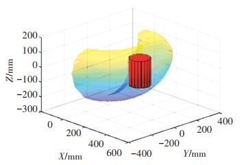
3.1 工作空间主操作手工作空间是衡量主操作手性能的一项重要指标,为保证医生在主从操作中顺利执行手术意图,主操作手工作空间必须大于手术要求的工作区域。主操作手的工作空间大小与主操作手各杆件尺寸成正比例相关,腹腔镜手术工作空间需求为一个半径r=80 mm,高度h=180 mm的圆柱体,限制主操作手杆件尺寸最小值分别为a2min=200 mm,a3min=150 mm,a4min=90 mm。主操作手最小工作空间如图 7所示,代表手术区域的圆柱体完全位于工作空间内部,满足手术需求。
|
图 7 主手最小运动空间与手术区域 Fig. 7 Minimum workspace and operation area |
雅可比矩阵表示了主操作手操作空间速度和关节空间速度之间的映射关系,雅可比矩阵中的每一行对应操作空间中的一个自由度,每一列对应主操作手的一个主动关节。基于雅可比矩阵的运动性能分析对主操作手的尺寸结构优化有重要意义,其表达式为
| $ \left[\begin{array}{l} \boldsymbol{v} \\ \boldsymbol{\omega} \end{array}\right]=\boldsymbol{J}({\theta}) \dot{\boldsymbol{\theta}}=\left[\begin{array}{l} \boldsymbol{J}_{v}(\theta) \\ \boldsymbol{J}_{\omega}(\theta) \end{array}\right]\left[\dot{\theta}_{1}, \dot{\theta}_{2} \cdots \dot{\theta}_{7}\right]^{\mathrm{T}} $ | (13) |
式中:v和ω分别为主手末端在操作空间中的线速度和角速度,
根据雅可比矩阵定义,求得线速度雅可比矩阵Jv(θ)和角速度雅可比矩阵Jω(θ),其具体表达式为:
| $ \boldsymbol{J}_{v}(\theta)=\left[\begin{array}{llllll} J_{11} & J_{12} & J_{13} & 0 & 0 & 0 \\ J_{21} & J_{22} & J_{23} & 0 & 0 & 0 \\ J_{31} & J_{32} & J_{33} & 0 & 0 & 0 \end{array}\right] $ | (14) |
| $ \left\{\begin{array}{l} J_{11}=-\mathrm{s} \theta_{1}\left[a_{3} \mathrm{c}\left(\theta_{2}+\theta_{3}\right)+a_{2} \mathrm{c} \theta_{2}+a_{4}\right] \\ J_{21}=\mathrm{c} \theta_{1}\left[a_{3} \mathrm{c}\left(\theta_{2}+\theta_{3}\right)+a_{2} \mathrm{c} \theta_{2}+a_{4}\right] \\ J_{31}=0 \\ J_{12}=-\mathrm{c} \theta_{1}\left[a_{3} \mathrm{s}\left(\theta_{2}+\theta_{3}\right)+a_{2} \mathrm{s} \theta_{2}\right] \\ J_{22}=-\mathrm{s} \theta_{1}\left[a_{3} \mathrm{s}\left(\theta_{2}+\theta_{3}\right)+a_{2} \mathrm{s} \theta_{2}\right] \\ J_{32}=a_{3} \mathrm{c}\left(\theta_{2}+\theta_{3}\right)+a_{2} \mathrm{c} \theta_{2} \\ J_{13}=-a_{3} \mathrm{c} \theta_{1} \mathrm{s}\left(\theta_{2}+\theta_{3}\right) \\ J_{23}=-a_{3} \mathrm{s} \theta_{1} \mathrm{s}\left(\theta_{2}+\theta_{3}\right) \\ J_{33}=a_{3} \mathrm{c}\left(\theta_{2}+\theta_{3}\right) \end{array}\right. $ | (15) |
| $ \begin{array}{l} \boldsymbol{J}_{\omega}(\theta)= \\ {\left[\begin{array}{cccccc} 0 & \mathrm{~s} \theta_{1} & \mathrm{~s} \theta_{1} & 0 & \mathrm{~s}\left(\theta_{1}-\theta_{5}\right) & \mathrm{c}\left(\theta_{1}-\theta_{5}\right) \mathrm{s} \theta_{6} \\ 0 & -\mathrm{c} \theta_{1} & -\mathrm{c} \theta_{1} & 0 & -\mathrm{c}\left(\theta_{1}-\theta_{5}\right) & \mathrm{s}\left(\theta_{1}-\theta_{5}\right) \mathrm{s} \theta_{6} \\ 1 & 0 & 0 & -1 & 0 & -\mathrm{c} \theta_{6} \end{array}\right]} \end{array} $ | (16) |
条件数是评价主操作手运动性能的一个重要指标,基于雅可比矩阵的条件数有多种表达方式,当采用谱范数时,定义如式(17)所示
| $ \kappa=\sigma_{\max } / \sigma_{\min } $ | (17) |
式中:σmax、σmin分别为雅可比矩阵J(θ)的最大和最小奇异值。条件数指标的含义为主操作手运动时各向同性的程度,从定义中不难看出κ∈[1, +∞),在使用时常取其倒数,即κ-1=1时表示机构各向同性,机构运动性能最优;κ-1趋于0时表示机构处于奇异位置。
此外,条件数还有一些其他含义:1)条件数同时是主手关节空间到操作空间的误差放大系数,可以反映出主操作手的运动精度;2)从控制角度来看,κ-1越小,机器人速度方程的病态程度就越大失控[23],不利于主从控制。综上所述,主操作手逆运动学的求解精度越差,会导致机器人条件数κ-1越接近于1,主操作手的运动性能和精度都越好。
但条件数是一种局部评价指标,只能反映主操作手末端在空间中某点的性能。为描述主操作手工作空间内整体的操作性能,Gosselin等[24]提出一种整体均值条件数指标,即全域性能指标来表示整体运动性能,表达式为
| $ \eta=\frac{\int\limits_{\omega} \frac{1}{\kappa} \mathrm{d} \omega}{\int\limits_{\omega} \mathrm{d} \omega} $ | (18) |
式中:κ为条件数,ω为主手工作空间。全域性能指标的取值范围为(0, 1],其数值越接近于1表示主操作手工作空间内的平均运动性能越好。但全域性能指标同样有其局限性,全域性能指标仅能代表整个工作空间的运动性能,不能反映灵巧度的波动状况。因此可能会出现主操作手工作空间中灵巧度高的区域与灵巧度低的区域存在较大差距的情况,为解决这一问题,引入全域性能波动指标,定义为
| $ \sigma=\sqrt{\frac{\int\limits_{\omega}\left(\frac{1}{\kappa}-\eta\right)^{2} \mathrm{~d} \omega}{\int\limits_{\omega} \mathrm{d} \omega}} $ | (19) |
基于方差分析法的全域性能波动指标反映了主操作手在工作空间内条件数的波动情况。主操作手的最高灵巧度区域通常位于工作空间的中心位置,并且距离工作空间中心位置越远,灵巧度越低。因此σ越大,工作空间中心的灵巧度和边缘的灵巧度之间的差距就越大;σ越小,中心与边缘之间的灵巧度差距就越小,运动性能越稳定。
综上所述,为保证主操作手在工作空间内既具备良好的整体灵巧度,又能够在运动中保持良好的稳定性,应使全域性能指标在其定义域内尽可能大,而全域性能波动指标则越小越好。据此定义主操作手综合性能指标:
| $ f=\eta-\sigma $ | (20) |
显然f取值越大,主操作手的综合运动性能越好。
但是,通过对主操作手单独杆件长度的分析可知,杆件长度的变化会引起全域性能指标和全域性能波动以相同趋势变大或变小,造成相反影响。例如当a2长度增加时,主操作手全域性能指标增大,具有更好的灵活性;但同时全域性能波动指标也增大,波动程度增加。而且在杆件的不同尺寸区间,这两种指标对杆件长度变化的敏感程度也不相同,是一种非线性变化。因此,需采用遗传算法对主操作手杆件尺寸进行优化。
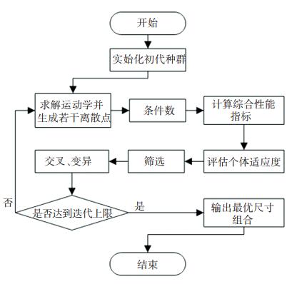
3.3 基于遗传算法的主操作手尺寸优化遗传算法结合了遗传学原理和自然选择机理,通过模拟自然法则达到搜索最优解的目的,非常适用于解决非线性优化问题。基于遗传算法对主操作手综合性能指标进行全局寻优,如图 8所示,求出主操作手运动性能最优的杆件尺寸组合。
|
图 8 主操作手遗传算法流程 Fig. 8 Flow chart of genetic algorithm for master manipulator |
遗传算法优化三要素分别为:
1) 设计变量。主操作手杆件尺寸a2、a3、a4。
2) 目标函数。f=η-σ→MAX。
3) 约束条件。200≤a2≤ 300, 150≤a3≤200, 90≤a4≤110。
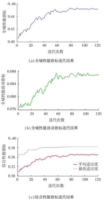
设置初始种群数量为200个,遗传迭代120次,结果如图 9所示,种群在80代左右趋于稳定。
|
图 9 遗传算法优化结果 Fig. 9 Optimization results of genetic algorithm |
根据遗传算法可得最优解为:fmax=0.382 3,此时各杆件尺寸为a2=266.08 mm,a3=151.69 mm,a4=92.02 mm。
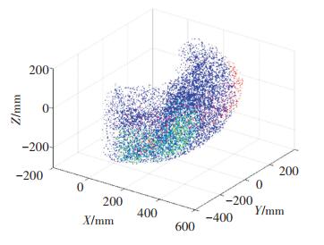
3.4 优化前后灵巧度分析为说明主操作手不同区域的运动性能,基于蒙特卡洛法分析各区域灵巧度,其条件数分布状况如图 10所示,红色表示运动性能较差,条件数κ < 0.3;蓝色表示运动性能中等,0.2≤κ < 0.5;绿色表示运动性能良好,κ≥0.5。
|
图 10 操作手灵巧度 Fig. 10 Dexterity of master manipulator |
优化前主操作手设计尺寸取约束条件中值,即a2=250 mm,a3=175 mm,a4=100 mm。此时的综合性能指标为fb=0.331 5。为直观表达,其灵巧度分析结果如图 11所示,其中图 11(a)(b)为其灵巧度投影在X-Y和X-Z平面的等高线图;图 11(c)为运动性能良好区域的轮廓和体积。

|
图 11 主操作手优化前灵巧度 Fig. 11 Dexterity of master manipulator before optimization |
优化后主操作手尺寸为a2=266.083 3 mm,a3=151.69 mm,a4=92.02 mm,对应综合性能指标为fmax=0.382 3。其灵巧度如图 12所示,图 12(a)(b)中虚线表示主操作手规定手术工作区域。

|
图 12 主操作手优化后灵巧度 Fig. 12 Dexterity of master manipulator after optimization |
通过优化前fb=0.331 5和优化后fmax=0.382 3对比可知,主操作手的综合性能指标提高了15.32%,灵巧度整体有明显改善,其峰值区域能够达到κ=0.6。尤其是运动性能良好区域,即κ≥0.5区域,体积显著增加,达到2.306 1×107 mm3,较优化前体积7.680 1×106 mm3相比,增加了约2倍。该区域可基本覆盖规定手术工作区域,使手术操作始终位于高灵巧度空间。
4 结论1) 提出了一种具备新型位姿解耦设计的8关节串联型主操作手,完成了该主操作手的机械结构设计。通过引入平行四边形机构产生的被动关节J4,以相反运动趋势补偿了J2和J3对末端姿态的影响,进一步解除了位姿的耦合关系;该主操作手同时具备力反馈功能,各个关节均配有一个直流伺服电机,采用绳传动方式进行减速增矩,为减小绳传动的传动误差,设计了一种预紧力快速调节机构。
2) 建立了主操作手的正逆运动学模型,分析了耦合关系,模型验证了该位姿解耦策略的正确性,同时说明了该位姿解耦设计可有效降低运动学建模过程中运算的复杂程度。
3) 为使主操作手具备良好的运动性能,综合考虑主操作手条件数的大小和波动程度,提出使用综合性能指标评价主操作手的运动性能;分析了主操作手杆长对评价指标的影响,并通过遗传算法对主操作手的杆件尺寸进行了优化。优化结果显示,主操作手的综合性能指标提高了15.32%,具备良好运动性能的工作空间体积增加到原来的3倍。主操作手在保证充足工作空间的基础上具备了良好的运动性能,为下一步主操作手样机搭建、控制系统设计和性能测试打下基础。
| [1] |
付宜利, 潘博. 微创外科手术机器人技术研究进展[J]. 哈尔滨工业大学学报, 2019, 51(1): 1. FU Yili, PAN Bo. Research progress of surgical robot for minimally invasive surgery[J]. Journal of Harbin Institute of Technology, 2019, 51(1): 1. DOI:10.11918/j.issn.0367-6234.201806178 |
| [2] |
LU Jiajia, DU Fuxin, ZHANG Tao, et al. An efficient inverse kinematics algorithm for continuum robot with a translational base[C]//2020 IEEE/ASME International Conference on Advanced Intelligent Mechatronics (AIM). Piscataway: IEEE, 2020: 1754. DOI: 10.1109/AIM43001.2020.9158792
|
| [3] |
LU Jiajia, DU Fuxin, YANG Fuchun, et al. Kinematic modeling of a class of n-tendon continuum manipulators[J]. Advanced Robotics, 2020, 34(19): 1254. DOI:10.1080/01691864.2020.1812427 |
| [4] |
BLACK D G, HOSSEINABADI A H H, SALCUDEANS E. 6-DOF force sensing for the master tool manipulator of the da Vinci Surgical system[J]. IEEE Robotics and Automation Letters, 2020, 5(2): 2264. DOI:10.1109/LRA.-2020.2970944 |
| [5] |
ZHANG Dandan, LIU Jindong, GAO Anzhu, et al. An ergonomic shared workspace analysis framework for the optimal placement of a compact master control console[J]. IEEE Robotics and Automation Letters, 2020, 5(2): 2995. DOI:10.1109/LRA.2020.2974428 |
| [6] |
TEKLEMARIAM H G, DAS A K. A case study of phantom omni force feedback device for virtual product design[J]. International Journal on Interactive Design and Manufacturing, 2017, 11(4): 881. DOI:10.1007/s12008-015-0274-3 |
| [7] |
贠今天, 陆晓璇, 从敬德. 主从式微创手术机器人系统附加反馈力补偿策略[J]. 天津工业大学学报, 2020, 39(4): 66. YUN Jintian, LU Xiaoxuan, CONG Jingde. Induced feedback force compensation strategy of master-slave minimal invasive surgical robotic system[J]. Journal of Tiangong University, 2020, 39(4): 66. DOI:10.3969/j.issn.1671-024x.2020.04.011 |
| [8] |
TOBERGTE A, HELMER P, HAGN U, et al. The sigma. 7 haptic interface for MiroSurge: a new bi-manual surgical console[C]//IEEE/RSJ International Conference on Intelligent Robots & Systems. Piscataway: IEEE, 2011: 3023. DOI: 10.1109/IROS.2011.6094433
|
| [9] |
FONTANELLI G A, FICUCIELLO F, VILLANI L, et al. Modelling and identification of the da Vinci Research Kit robotic arms[C]//2017 IEEE/RSJ International Conference on Intelligent Robots and Systems. Piscataway: IEEE, 2017: 1461. DOI: 10.1109/IROS.2017.8205948
|
| [10] |
LIN Hongbin, HUI C W V, WANG Yan, et al. A reliable gravity compensation control strategy for dvrk robotic arms with nonlinear disturbance forces[J]. IEEE Robotics and Automation Letters, 2019, 4(4): 3892. DOI:10.1109/LRA.2019.2927953 |
| [11] |
WISANUVEJ P, GRAS G, LEIBRANDT K, et al. Master manipulator designed for highly articulated robotic instruments in single access surgery[C]//2017 IEEE/RSJ International Conference on Intelligent Robots and Systems. Piscataway: IEEE, 2017: 209. DOI: 10.1109/IROS.2017.8202159
|
| [12] |
LEE H, CHEON B, HWANG M, et al. A master manipulator with a remote-center-of-motion kinematic structure for a minimally invasive robotic surgical system[J]. The International Journal of Medical Robotics and Computer Assisted Surgery, 2018, 14(1): e1865. DOI:10.1002/rcs.1865 |
| [13] |
WANG Tao, PAN Bo, FU Yili, et al. Design of a new haptic device and experiments in minimally invasive surgical robot[J]. Computer Assisted Surgery, 2017, 22(1): 240. DOI:10.1080/24699322.2017.1389402 |
| [14] |
王涛, 潘博, 付宜利, 等. 微创手术机器人力反馈主手重力补偿研究[J]. 机器人, 2020, 42(5): 525. WANG Tao, PAN Bo, FU Yili, et al. Gravity compensation for the force reflection manipulator of minimally invasive surgical robot[J]. Robot, 2020, 42(5): 525. DOI:10.13973/j.cnki.robot.190547 |
| [15] |
LIANG Yunlei, SUN Lining, DU Zhijiang, et al. Mechanism design and optimization of a haptic master manipulator for laparoscopic surgical robots[J]. IEEE Access, 2019, 7: 147808. DOI:10.1109/ACCESS.2019.2943622 |
| [16] |
SANG Hongqiang, WANG Shuxin, LI Jianmin, et al. Control design and implementation of a novel master-slave surgery robot system, MicroHand A[J]. The International Journal of Medical Robotics and Computer Assisted Surgery, 2011, 7(3): 334. DOI:10.1002/rcs.403 |
| [17] |
李建民. 微创机器人机构设计方法与主从映射策略研究[D]. 天津: 天津大学, 2012 LI Jianmin. Mechanism design and master-slave mapping strategy of minimally invasive surgical robot[D]. Tianjin: Tianjin University, 2012 |
| [18] |
桑宏强, 安达, 张新建. 主操作手结构设计及运动学参数标定[J]. 机械传动, 2019, 43(10): 56. SANG Hongqiang, AN Da, ZHANG Xinjian. Structure design and kinematics parameter calibration of master manipulator[J]. Journal of Mechanical Transmission, 2019, 43(10): 56. DOI:10.16578/j.issn.1004.2539.2019.10.011 |
| [19] |
谢宏伟, 陶忠, 侯军占, 等. 多绳精密传动的传动精度实验研究[J]. 兵工学报, 2017, 38(4): 728. XIE Hongwei, TAO Zhong, HOU Junzhan, et al. Experimental research on transmission accuracy of multi-cable drive[J]. Acta Armamentarii, 2017, 38(4): 728. DOI:10.3969/j.issn.1000-1093.2017.04.014 |
| [20] |
金忠庆. 钢丝绳精密传动机构的分析与实验研究[D]. 长沙: 国防科学技术大学, 2006 JIN Zhongqing. Analysis and research on precise steel cable driver[D]. Changsha: National University of Defense Technology, 2006 |
| [21] |
陈旭. 微创手术机器人力反馈型主手设计与控制研究[D]. 哈尔滨: 哈尔滨工业大学, 2018. CHEN Xu. Design andcontrol of a force-feedback master manipulator for minimally invasive surgery[D]. Harbin: Harbin Institute of Technology, 2018 |
| [22] |
WANG Tao, PAN Bo, TANG Zhaokun, et al. Design and analysis of a force reflection master manipulator forminimally invasive surgical robot[C]//2014 IEEE International Conference on Robotics and Biomimetics. Piscataway: IEEE, 2014: 58. DOI: 10.1109/ROBIO.2014.7090307
|
| [23] |
ZHANG Pu, YAO Zhenqiang, DU Zhengchun. Global performance index system for kinematic optimization of robotic mechanism[J]. Journal of Mechanical Design, 2014, 136(3): 031001. DOI:10.1115/1.4026031 |
| [24] |
GOSSELIN C, ANGELES J. A global performance index for the kinematic optimization of robotic manipulators[J]. Journal of Mechanical Design, 1991, 113(3): 220. DOI:10.1115/1.2912772 |
 2021, Vol. 53


