节理裂隙作为一种普遍存在于岩体中的缺陷结构,对应力波(爆炸波、地震波等)在岩体中的传播规律产生较大影响。应力波与节理之间的作用关系复杂,常常导致振幅下降、波形变化和能量损失[1-2]。岩体中的天然裂隙常常由饱和砂土、黏土以及风化岩石等具有黏弹性变形特性的介质填充,在自然条件下逐渐演化成黏弹性节理,故研究具有黏弹特性的节理对应力波传播的影响机制在抗震工程、损伤测定和岩石力学等领域都具有重大意义。
国内外学者针对应力波在节理岩体中的传播过程进行了大量研究。王志亮等[3]提出了一种三参数模型用于描述节理岩体的动态响应,基于位移不连续理论(DDM)推导了一维应力波的传播方程并与实验进行对比,发现当应力波持续时间较短时,理论结果与实验结果吻合较好。Li等[4-7]根据波前动量守恒原理提出了一种新的时域递归方法,相继导出了应力波通过线弹性节理、非线弹性节理以及考虑节理切向滑移特性时的传播方程。而对于天然夹层裂隙中常常充填有饱和砂土、黏土等形成的节理,Fehler等[8-9]认为应考虑其黏弹特性,对此,也有不少学者进行了相关研究。Huang等[10]利用矩阵传播法研究了应力波通过一组黏弹性节理的传播规律,发现在Kelvin节理中存在一个特定黏度系数值使得能量耗散率最大。Yi等[11]采用等效介质法将节理充填介质等效为静态的各向同性介质,发现该方法不能准确反映填充介质较疏时的振幅各向异性和波速随频率变化的规律。Zhu等[12]考虑填充介质质量产生的惯性应力,提出了位移与应力不连续理论(DSDM),发现应力波通过填充节理时的能量耗散率由节理黏度系数和填充介质质量决定。Wu等[13]使用分离式霍普金森岩杆对充填节理进行的动态试验结果表明,DSDM比DDM更适合描述厚度在10 mm以上的填充节理对波传播的影响。此外,Li等[14-16]提出了一种薄层界面模型用于研究应力波入射充填节理时的传播规律,结果表明,在剪切波入射该模型引起剪应力大于薄层界面的抗剪强度而产生滑移时该方法仍有效。
综上,目前基于时域递归方法(TDRM)且考虑应力不连续条件的平行黏弹性节理中波传播特性研究开展较少。因此,本研究先采用TDRM法,引入饱依丁-汤姆逊本构模型描述节理的黏弹特性,并考虑填充节理质量,将DDM扩展至DSDM,导出了应力波在一组平行黏弹性节理中传播的完整解析方程。通过与频域内的封闭解对比验证该方法的正确性。最后, 分析了节理模型参数、无量纲节理厚度和平行节理间距等参数对透反射系数和能量耗散率的影响,力求得出有参考价值的结论。
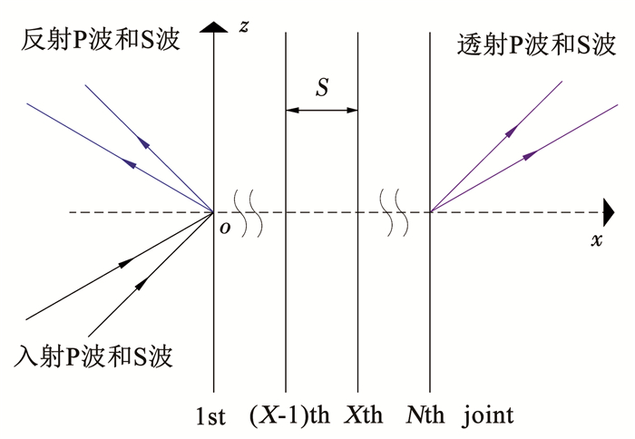
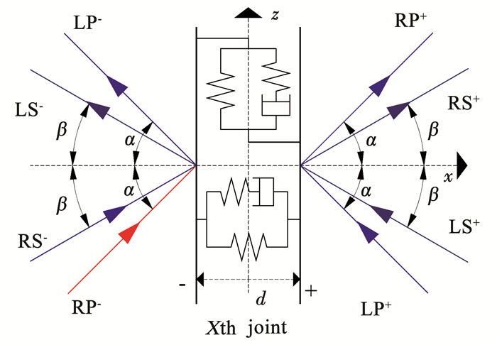
1 理论分析 1.1 问题描述在离爆炸、地震等扰动源较远的地层中,应力波相对于节理面可看作平面波。当应力波穿过一组等间距平行节理时,在节理处会发生透射和反射现象,分别形成透射P波与S波,反射P波与S波,如图 1所示,S为节理间距。图 2为应力波通过第X条节理的左右波形图。其中,d为节理厚度,符号“-”和“+”分别代表节理的左侧与右侧,LP-、LS-、RP-和RS-分别为节理左侧的左行P波、左行S波、右行P波和右行S波,LP+、LS+、RP+和RS+分别为节理右侧的左行P波、左行S波、右行P波和右行S波。假设节理两侧的岩石均为线弹性介质,且密度与泊松比相同,P波入射角为α,S波入射角为β。应力波通过含黏弹特性的充填介质时,会产生一定的边际弥散效应而损失部分到达节理右侧的能量。本研究不考虑应力波入射充填节理时产生的散射效应,认为该透反射过程遵循Snell定律。故右侧出射波角度与左侧入射角相同,即透反射P波和S波与法线夹角均分别为α和β[12, 15, 17]。
|
图 1 应力波通过平行节理 Fig. 1 Stress wave traversing through parallel joint |
|
图 2 第X条节理两侧的左行波和右行波 Fig. 2 Left- and right-running waves on both sides of the Xth joint |
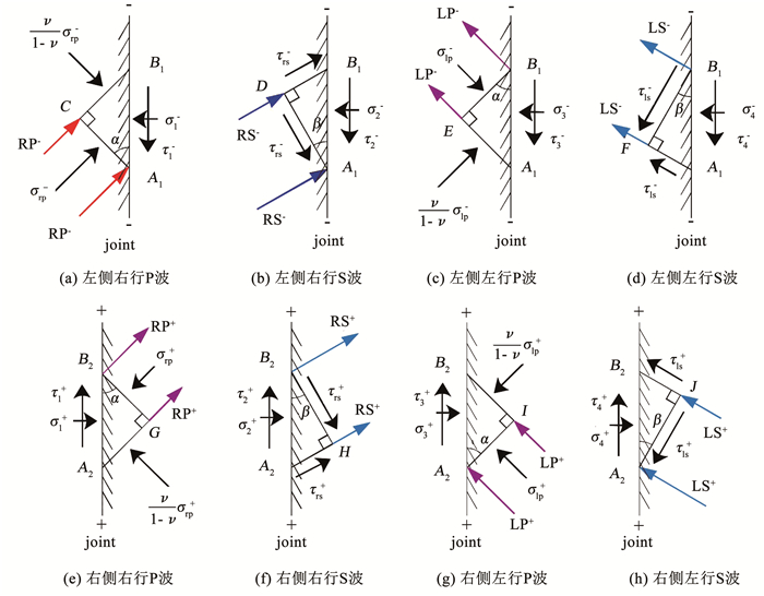
当应力波通过第X条节理时,不考虑体力的影响,选取节理两侧的微单元如图 3(a)~3(h)所示。当右行P波到达节理面的左侧时,选取图 3(a)中微单元A1B1C进行力学分析,A1B1为节理左侧界面,A1C为波前,B1C为波束面。σ1-和τ1-分别表示左侧节理面上的法向应力和切向应力,σrp-表示右行P波的波前正应力。由于该问题被简化为平面应变问题,微单元侧面B1C上应力为
| $ \sigma_{1}^{-}-\sigma_{\mathrm{rp}}^{-} \cos ^{2} \alpha-\frac{\nu}{1-\nu} \sigma_{\mathrm{rp}}^{-} \sin ^{2} \alpha=0 $ | (1) |
| $ \tau_{1}^{-}-\sigma_{\mathrm{rp}}^{-} \sin \alpha \cos \alpha+\frac{\nu}{1-\nu} \sigma_{\mathrm{rp}}^{-} \cos \alpha \sin \alpha=0 $ | (2) |
|
图 3 应力波波前与节理两侧应力 Fig. 3 Stress on wavefront and rock joint surfaces |
根据Snell定律
| $ \frac{\sin \beta}{\sin \alpha}=\frac{c_{\mathrm{s}}}{c_{\mathrm{p}}}=\sqrt{\frac{1-2 \nu}{2(1-\nu)}} $ | (3) |
式中:cp和cs分别为P波和S波在岩石中的波速。图 3(b)~3(h)分析过程同图 3(a)。
结合上述结果及波前动量守恒原理,根据Li等[4]推导过程可得节理两侧的法向应力、切向应力、法向速度与切向速度:
| $ \sigma^{e}=z_{\mathrm{p}} \cos 2 \beta v_{\mathrm{rp}}^{e}+z_{\mathrm{s}} \sin 2 \beta v_{\mathrm{rs}}^{e}+z_{\mathrm{p}} \cos 2 \beta v_{\mathrm{lp}}^{e}-z_{\mathrm{s}} \sin 2 \beta v_{\mathrm{ls}}^{e} $ | (4) |
| $ \begin{aligned} \tau^{e}=&\left(z_{\mathrm{p}} \sin 2 \beta \tan \beta / \tan \alpha\right) v_{\mathrm{rp}}^{e}-\left(z_{\mathrm{s}} \cos 2 \beta\right) v_{\mathrm{rs}}^{e}-\\ &\left(z_{\mathrm{p}} \sin 2 \beta \tan \beta / \tan \alpha\right) v_{\mathrm{lp}}^{e}-\left(z_{\mathrm{s}} \cos 2 \beta\right) v_{\mathrm{ls}}^{e} \end{aligned} $ | (5) |
| $ v_{\mathrm{n}}^{e}=\cos \alpha v_{\mathrm{rp}}^{e}+\sin \beta v_{\mathrm{rs}}^{e}-\cos \alpha v_{\mathrm{lp}}^{e}+\sin \beta v_{\mathrm{ls}}^{e} $ | (6) |
| $ v_{\mathtt{τ}}^{e}=\sin \alpha v_{\mathrm{rp}}^{e}-\cos \beta v_{\mathrm{rs}}^{e}+\sin \alpha v_{\mathrm{lp}}^{e}+\cos \beta v_{\mathrm{ls}}^{e} $ | (7) |
式中:上标e分别代表“-”或“+”。下标r和l分别代表右行波和左行波。
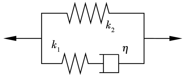
本研究引入饱依丁-汤姆逊本构模型对岩体节理的黏弹特性进行描述,如图 4所示。由一个Maxwell体与弹簧元件并联而成,本构方程为
| $ \eta\left(k_{1}+k_{2}\right) \dot{\varepsilon}+k_{1} k_{2} \varepsilon=\dot{\eta \sigma}+k_{1} \sigma $ | (8) |
式中:σ为应力,ε为应变,
节理左右界面的连接如图 2所示,考虑节理填充介质质量的应力不连续条件[12, 19]:
| $ \left\{\begin{array}{l} \sigma^{-}-\sigma^{+}=m_{\mathrm{n}} a_{\mathrm{n}} \\ \tau^{-}-\tau^{+}=m_{\mathtt{τ}} a_{\mathtt{τ}} \end{array}\right. $ | (9) |
式中:mn和mτ分别为法向质量和切向质量。法向质量代表节理厚度、单位面积和密度的乘积,mn=ρ0d。而切向质量与法线质量之间的数量关系主要取决于入射角度和填充介质的波速,mτ=qmn=[1-(cplate/c)2sin2θ]mn。ρ0为填充介质密度,c和θ分别为相应入射波波速和入射角,cplate为介质平面纵波速度,由
| $ \begin{gathered} \eta\left(k_{1}+k_{2}\right) \frac{\partial v^{-}-\partial v^{+}}{\partial t}+k_{1} k_{2} \frac{\partial u^{-}-\partial u^{+}}{\partial t}= \\ \eta \frac{\partial^{2} \sigma^{+}}{\partial t^{2}}+k_{1} \frac{\partial \sigma^{+}}{\partial t} \end{gathered} $ | (10) |
将式(10)作为连接节理左右两侧法向和切向的位移不连续条件可以得
| $ \left\{\begin{array}{l} \eta_{\mathrm{n}}\left(k_{\mathrm{n} 1}+k_{\mathrm{n} 2}\right) \frac{\partial\left(v_{\mathrm{n}(i)}^{-}-v_{\mathrm{n}(i)}^{+}\right)}{\partial t}+k_{\mathrm{n} 1} k_{\mathrm{n} 2}\left(v_{\mathrm{n}(i)}^{-}-v_{\mathrm{n}(i)}^{+}\right)=\eta_{\mathrm{n}} \frac{\partial^{2} \sigma_{(i)}^{+}}{\partial t^{2}}+k_{\mathrm{n} 1} \frac{\partial \sigma_{(i)}^{+}}{\partial t} \\ \eta_{\mathtt{τ}}\left(k_{\mathtt{τ} 1}+k_{\mathtt{τ} 2}\right) \frac{\partial\left(v_{\mathtt{τ}(i)}^{-}-v_{\mathtt{τ}(i)}^{+}\right)}{\partial t}+k_{\mathtt{τ} 1} k_{\mathtt{τ} 2}\left(v_{\mathtt{τ}(i)}^{-}-v_{\mathtt{τ}(i)}^{+}\right)=\eta_{\mathtt{τ}} \frac{\partial^{2} \tau_{(i)}^{+}}{\partial t^{2}}+k_{\mathtt{τ} 1} \frac{\partial \tau_{(i)}^{+}}{\partial t} \end{array}\right. $ | (11) |
将式(4)~(7)代入式(9)和(11),并整理为矩阵形式:
| $ \boldsymbol{A}\left[\begin{array}{c} v_{\mathrm{rp}}^{-} \\ v_{\mathrm{rs}}^{-} \end{array}\right]_{i+1, X}+\boldsymbol{B}\left[\begin{array}{c} v_{\mathrm{lp}}^{-} \\ v_{\mathrm{ls}}^{-} \end{array}\right]_{i+1, X}+\boldsymbol{C}\left[\begin{array}{c} v_{\mathrm{rp}}^{+} \\ v_{\mathrm{rs}}^{+} \end{array}\right]_{i+1, X}+\boldsymbol{D}\left[\begin{array}{c} v_{\mathrm{lp}}^{+} \\ v_{\mathrm{ls}}^{+} \end{array}\right]_{i+1, X}=\boldsymbol{E}\left[\begin{array}{c} v_{\mathrm{rp}}^{+} \\ v_{\mathrm{rs}}^{+} \end{array}\right]_{i, X}+\boldsymbol{F}\left[\begin{array}{c} v_{\mathrm{lp}}^{+} \\ v_{\mathrm{ls}}^{+} \end{array}\right]_{i, X} $ | (12) |
| $ \begin{gathered} \boldsymbol{A}_{1}\left[\begin{array}{c} v_{\mathrm{rp}}^{+} \\ v_{\mathrm{rs}}^{+} \end{array}\right]_{i+1, X}+\boldsymbol{B}_{1}\left[\begin{array}{c} v_{\mathrm{lp}}^{+} \\ v_{\mathrm{ls}}^{+} \end{array}\right]_{i+1, X}+\boldsymbol{C}_{1}\left[\begin{array}{c} v_{\mathrm{rp}}^{+} \\ v_{\mathrm{rs}}^{+} \end{array}\right]_{i, X}+\boldsymbol{D}_{1}\left[\begin{array}{c} v_{\mathrm{lp}}^{+} \\ v_{\mathrm{ls}}^{+} \end{array}\right]_{i, X}+\boldsymbol{E}_{1}\left[\begin{array}{c} v_{\mathrm{rp}}^{+} \\ v_{\mathrm{rs}}^{+} \end{array}\right]_{i-1, X}+\boldsymbol{F}_{1}\left[\begin{array}{l} v_{\mathrm{lp}}^{+} \\ v_{\mathrm{ls}}^{+} \end{array}\right]_{i-1, X}= \\ \boldsymbol{G}_{1}\left[\begin{array}{c} v_{\mathrm{rp}}^{-} \\ v_{\mathrm{rs}}^{-} \end{array}\right]_{i+1, X}+\boldsymbol{H}_{1}\left[\begin{array}{l} v_{\mathrm{lp}}^{-} \\ v_{\mathrm{ls}}^{-} \end{array}\right]_{i+1, X}+\boldsymbol{I}_{1}\left[\begin{array}{l} v_{\mathrm{rp}}^{-} \\ v_{\mathrm{rs}}^{-} \end{array}\right]_{i, X}+\boldsymbol{J}_{1}\left[\begin{array}{l} v_{\mathrm{lp}}^{-} \\ v_{\mathrm{ls}}^{-} \end{array}\right]_{i, X} \end{gathered} $ | (13) |
式中的相关系数矩阵如下:
| $ \boldsymbol{A}=\left[\begin{array}{l} z_{\mathrm{p}} \cos 2 \beta & \ \ \ z_{\mathrm{s}} \sin 2 \beta \\ z_{\mathrm{p}} \sin 2 \beta \tan \beta / \tan \alpha & -z_{\mathrm{s}} \cos 2 \beta \end{array}\right], \boldsymbol{B}=\left[\begin{array}{l} \ \ \ z_{\mathrm{p}} \cos 2 \beta & -z_{\mathrm{s}} \sin 2 \beta \\ -z_{\mathrm{p}} \sin 2 \beta \tan \beta / \tan \alpha & -z_{\mathrm{s}} \cos 2 \beta \end{array}\right], $ |
| $ \boldsymbol{C}=\left[\begin{array}{l} -z_{\mathrm{p}} \cos 2 \beta-\frac{m_{\mathrm{n}}}{\Delta t} \cos \alpha & -z_{\mathrm{s}} \sin 2 \beta-\frac{m_{\mathrm{n}}}{\Delta t} \sin \beta \\ -z_{\mathrm{p}} \sin 2 \beta \tan \beta / \tan \alpha-\frac{m_{\mathrm{s}}}{\Delta t} \sin \alpha & \ \ \ z_{\mathrm{s}} \cos 2 \beta+\frac{m_{\mathrm{s}}}{\Delta t} \cos \beta \end{array}\right], \boldsymbol{D}=\left[\begin{array}{l} -z_{\mathrm{p}} \cos 2 \beta+\frac{m_{\mathrm{n}}}{\Delta t} \cos \alpha & z_{\mathrm{s}} \sin 2 \beta-\frac{m_{\mathrm{n}}}{\Delta t} \sin \beta \\ \ \ \ z_{\mathrm{p}} \sin 2 \beta \tan \beta / \tan \alpha-\frac{m_{\mathrm{s}}}{\Delta t} \sin \alpha & z_{\mathrm{s}} \cos 2 \beta-\frac{m_{\mathrm{s}}}{\Delta t} \cos \beta \end{array}\right], $ |
| $ \boldsymbol{E}=\left[\begin{array}{l} -\frac{m_{\mathrm{n}}}{\Delta t} \cos \alpha & -\frac{m_{\mathrm{n}}}{\Delta t} \sin \beta \\ -\frac{m_{\mathrm{s}}}{\Delta t} \sin \alpha & \ \ \ \frac{m_{\mathrm{s}}}{\Delta t} \cos \beta \end{array}\right], \boldsymbol{F}=\left[\begin{array}{l} \ \ \ \frac{m_{\mathrm{n}}}{\Delta t} \cos \alpha & -\frac{m_{\mathrm{n}}}{\Delta t} \sin \beta \\ -\frac{m_{\mathrm{s}}}{\Delta t} \sin \alpha & -\frac{m_{\mathrm{s}}}{\Delta t} \cos \beta \end{array}\right], $ |
| $ \boldsymbol{A}_{1}=\left[\begin{array}{ll} \left(k_{\mathrm{n} 1}+\frac{\eta_{\mathrm{n}}}{\Delta t}\right) z_{\mathrm{p}} \cos 2 \beta+\eta_{\mathrm{n}}\left(k_{\mathrm{n} 1}+k_{\mathrm{n} 2}\right) \cos \alpha & \ \ \ \left(k_{\mathrm{n} 1}+\frac{\eta_{\mathrm{n}}}{\Delta t}\right) z_{\mathrm{s}} \sin 2 \beta+\eta_{\mathrm{n}}\left(k_{\mathrm{n} 1}+k_{\mathrm{n} 2}\right) \sin \beta \\ \left(k_{\mathtt{τ} 1}+\frac{\eta_{\mathtt{τ}}}{\Delta t}\right) z_{\mathrm{p}} \sin 2 \beta \tan \beta / \tan \alpha+\eta_{\mathtt{τ}}\left(k_{\mathtt{τ} 1}+k_{\mathtt{τ} 2}\right) \sin \alpha & -\left(k_{\mathtt{τ} 1}+\frac{\eta_{\mathtt{τ}}}{\Delta t}\right) z_{\mathrm{s}} \cos 2 \beta-\eta_{\mathtt{τ}}\left(k_{\mathtt{τ} 1}+k_{\mathtt{τ} 2}\right) \cos \beta \end{array}\right], $ |
| $ \boldsymbol{B}_{1}=\left[\begin{array}{ll} \ \ \ \left(k_{\mathrm{n} 1}+\frac{\eta_{\mathrm{n}}}{\Delta t}\right) z_{\mathrm{p}} \cos 2 \beta-\eta_{\mathrm{n}}\left(k_{\mathrm{n1}}+k_{\mathrm{n} 2}\right) \cos \alpha & -\left(k_{\mathrm{n} 1}+\frac{\eta_{\mathrm{n}}}{\Delta t}\right) z_{\mathrm{s}} \sin 2 \beta+\eta_{\mathrm{n}}\left(k_{\mathrm{n1}}+k_{\mathrm{n} 2}\right) \sin \beta \\ -\left(k_{\mathtt{τ} 1}+\frac{\eta_{\mathtt{τ}}}{\Delta t}\right) z_{\mathrm{p}} \sin 2 \beta \tan \beta / \tan \alpha+\eta_{\mathtt{τ}}\left(k_{\mathtt{τ} 1}+k_{\mathtt{τ} 2}\right) \sin \alpha & -\left(k_{\mathtt{τ} 1}+\frac{\eta_{\mathtt{τ}}}{\Delta t}\right) z_{\mathrm{s}} \cos 2 \beta+\eta_{\mathtt{τ}}\left(k_{\mathtt{τ} 1}+k_{\mathtt{τ} 2}\right) \cos \beta \end{array}\right], $ |
| $ \boldsymbol{C}_{1}=\left[\begin{array}{ll} -\left(k_{\mathrm{n1}}+\frac{2 \eta_{\mathrm{n}}}{\Delta t}\right) z_{\mathrm{p}} \cos 2 \beta+\left[k_{\mathrm{n1}} k_{\mathrm{n} 2} \Delta t-\eta_{\mathrm{n}}\left(k_{\mathrm{n1}}+k_{\mathrm{n} 2}\right)\right] \cos \alpha & -\left(k_{\mathrm{n1}}+\frac{2 \eta_{\mathrm{n1}}}{\Delta t}\right) z_{\mathrm{s}} \sin 2 \beta+\left[k_{\mathrm{n1}} k_{\mathrm{n} 2} \Delta t-\eta_{\mathrm{n}}\left(k_{\mathrm{n1}}+k_{\mathrm{n} 2}\right)\right] \sin \beta \\ -\left(k_{\mathtt{τ} 1}+\frac{2 \eta_{\mathtt{τ}}}{\Delta t}\right) z_{\mathrm{p}} \sin 2 \beta \tan \beta / \tan \alpha+\left[k_{\mathtt{τ} 1} k_{\mathtt{τ} 2} \Delta t-\eta_{\mathtt{τ}}\left(k_{\mathtt{τ}1}+k_{\mathtt{τ} 2}\right)\right] \sin \alpha & \ \ \ \left(k_{\mathtt{τ} 1}+\frac{2 \eta_{\mathtt{τ} 1}}{\Delta t}\right) z_{\mathrm{s}} \cos 2 \beta+\left[-k_{\mathtt{τ}1} k_{\mathtt{τ} 2} \Delta t+\eta_{\mathtt{τ}}\left(k_{\mathtt{τ}1}+k_{\mathtt{τ} 2}\right)\right] \cos \beta \end{array}\right], $ |
| $ \boldsymbol{D}_{1}=\left[\begin{array}{ll} -\left(k_{\mathrm{n1}}+\frac{2 \eta_{\mathrm{n}}}{\Delta t}\right) z_{\mathrm{p}} \cos 2 \beta+\left[-k_{\mathrm{n1}} k_{\mathrm{n} 2} \Delta t+\eta_{\mathrm{n}}\left(k_{\mathrm{n1}}+k_{\mathrm{n2}}\right)\right] \cos \alpha & \left(k_{\mathrm{n1}}+\frac{2 \eta_{\mathrm{n}}}{\Delta t}\right) z_{\mathrm{s}} \sin 2 \beta+\left[k_{\mathrm{n1}} k_{\mathrm{n} 2} \Delta t-\eta_{\mathrm{n}}\left(k_{\mathrm{n1}}+k_{\mathrm{n} 2}\right)\right] \sin \beta \\ \ \ \ \left(k_{\mathtt{τ} 1}+\frac{2 \eta_{\mathtt{τ}}}{\Delta t}\right) z_{\mathrm{p}} \sin 2 \beta \tan \beta / \tan \alpha+\left[-k_{\mathtt{τ} 1} k_{\mathtt{τ} 2} \Delta t+\eta_{\mathtt{τ}}\left(k_{\mathtt{τ} 1}+k_{\mathtt{τ} 2}\right)\right] \sin \alpha & \left(k_{\mathtt{τ} 1}+\frac{2 \eta_{\mathtt{τ}}}{\Delta t}\right) z_{\mathrm{s}} \cos 2 \beta+\left[k_{\mathtt{τ} 1} k_{\mathtt{τ} 2} \Delta t-\eta_{\mathtt{τ}}\left(k_{\mathtt{τ} 1}+k_{\mathtt{τ} 2}\right)\right] \cos \beta \end{array}\right], $ |
| $ \boldsymbol{E}_{1}=\left[\begin{array}{ll} \frac{\eta_{\mathrm{n}}}{\Delta t} z_{\mathrm{p}}\cos 2 \beta & \ \ \ \frac{\eta_{\mathrm{n}}}{\Delta t} z_{\mathrm{s}} \sin 2 \beta \\ \frac{\eta_{\mathtt{τ}}}{\Delta t} z_{\mathrm{p}}\sin 2 \beta \tan \beta / \tan \alpha & -\frac{\eta_{\tau}}{\Delta t} z_{\mathrm{s}} \cos 2 \beta \end{array}\right], \boldsymbol{F}_{1}=\left[\begin{array}{l} \ \ \ \frac{\eta_{\mathrm{n}}}{\Delta t} z_{\mathrm{p}} \cos 2 \beta & -\frac{\eta_{\mathrm{n}}}{\Delta t} z_{\mathrm{s}} \sin 2 \beta \\ -\frac{\eta_{\mathtt{τ}}}{\Delta t} z_{\mathrm{p}} \sin 2 \beta \tan \beta / \tan \alpha & -\frac{\eta_{\mathtt{τ}}}{\Delta t} z_{\mathrm{s}} \cos 2 \beta \end{array}\right], $ |
| $ \boldsymbol{G}_{1}=\left[\begin{array}{l} \eta_{\mathrm{n}}\left(k_{\mathrm{n} 1}+k_{\mathrm{n} 2}\right) \cos \alpha & \ \ \ \eta_{\mathrm{n}}\left(k_{\mathrm{n} 1}+k_{\mathrm{n} 2}\right) \sin \beta \\ \eta_{\mathtt{τ}}\left(k_{\mathtt{τ} 1}+k_{\mathtt{τ} 2}\right) \sin \alpha & -\eta_{\mathtt{τ}}\left(k_{\mathtt{τ} 1}+k_{\mathtt{τ} 2}\right) \cos \beta \end{array}\right], \boldsymbol{H}_{1}=\left[\begin{array}{l} -\eta_{\mathrm{n}}\left(k_{\mathrm{n} 1}+k_{\mathrm{n} 2}\right) \cos \alpha & \eta_{\mathrm{n}}\left(k_{\mathrm{n} 1}+k_{\mathrm{n} 2}\right) \sin \beta \\ \ \ \ \eta_{\mathtt{τ}}\left(k_{\mathtt{τ} 1}+k_{\mathtt{τ} 2}\right) \sin \alpha & \eta_{\mathtt{τ}}\left(k_{\mathtt{τ} 1}+k_{\mathtt{τ} 2}\right) \cos \beta \end{array}\right], $ |
| $ \boldsymbol{I}_{1}=\left[\begin{array}{ll} {\left[k_{\mathrm{n} 1} k_{\mathrm{n} 2} \Delta t-\eta_{\mathrm{n}}\left(k_{\mathrm{n} 1}+k_{\mathrm{n} 2}\right)\right] \cos \alpha} & {\left[k_{\mathrm{n} 1} k_{\mathrm{n} 2} \Delta t-\eta_{\mathrm{n}}\left(k_{\mathrm{n} 1}+k_{\mathrm{n} 2}\right)\right] \sin \beta} \\ {\left[k_{\mathtt{τ} 1} k_{\mathtt{τ} 2} \Delta t-\eta_{\mathtt{τ}}\left(k_{\mathtt{τ} 1}+k_{\mathtt{τ} 2}\right)\right] \sin \alpha} & {\left[-k_{\mathtt{τ} 1} k_{\mathtt{τ} 2} \Delta t+\eta_{\mathtt{τ}}\left(k_{\mathtt{τ} 1}+k_{\mathtt{τ} 2}\right)\right] \cos \beta} \end{array}\right], $ |
| $ \boldsymbol{J}_{1}=\left[\begin{array}{ll} {\left[-k_{\mathrm{n} 1} k_{\mathrm{n} 2} \Delta t+\eta_{\mathrm{n}}\left(k_{\mathrm{n} 1}+k_{\mathrm{n} 2}\right)\right] \cos \alpha} & {\left[k_{\mathrm{n1}} k_{\mathrm{n} 2} \Delta t-\eta_{\mathrm{n}}\left(k_{\mathrm{n} 1}+k_{\mathrm{n} 2}\right)\right] \sin \beta} \\ {\left[k_{\mathtt{τ} 1} k_{\mathtt{τ} 2} \Delta t-\eta_{\mathtt{τ}}\left(k_{\mathtt{τ} 1}+k_{\mathtt{τ} 2}\right)\right] \sin \alpha} & {\left[k_{\mathtt{τ} 1} k_{\mathtt{τ} 2} \Delta t-\eta_{\mathtt{τ}}\left(k_{\mathtt{τ} 1}+k_{\mathtt{τ} 2}\right)\right] \cos \beta} \end{array}\right] $ |
假定节理间的岩石为完全弹性,则应力波由第X-1条节理右侧出射到达第X条节理左侧或由第X+1条节理左侧反射至第X条节理右侧的过程中,只相差一个时间差,故时移函数方程表达式为
| $ \left\{\begin{array}{l} v_{\mathrm{rp}, X}^{-}(t)=v_{\mathrm{rp}, X-1}^{+}\left(t-\frac{S}{\cos \alpha \cdot c_{\mathrm{p}}}\right) \\ v_{\mathrm{rs}, X}^{-}(t)=v_{\mathrm{rs}, X-1}^{+}\left(t-\frac{S}{\cos \beta \cdot c_{\mathrm{s}}}\right) \end{array}\right. $ | (14) |
| $ \left\{\begin{array}{l} v_{\mathrm{lp}, X}^{+}(t)=v_{\mathrm{lp}, X+1}^{-}\left(t-\frac{S}{\cos \alpha \cdot c_{\mathrm{p}}}\right) \\ v_{\mathrm{ls}, X}^{+}(t)=v_{\mathrm{ls}, X+1}^{-}\left(t-\frac{S}{\cos \beta \cdot c_{\mathrm{s}}}\right) \end{array}\right. $ | (15) |
式中:下标X表示第X条节理, S表示相邻节理间的间距。在计算过程中,时间步长为Δt,则两侧速度时移步数差为np=S/(cos α·cp·Δt)或ns=S/(cos β·cs·Δt)。
式(12)~(15)即为应力波在一组平行节理中传播的完整方程。通过编制MATLAB程序,输入相应已知条件和初始条件并采用满足精度要求的时间步长,对上述方程进行时域递归计算即可得解。
2 理论验证为方便研究节理对应力波在岩体中传播特征的影响,定义反射和透射系数分别为
| $ R_{a b, N}=\frac{\max \left|v_{\mathrm{l} a, 1}^{-}\right|}{\max \left|v_{\mathrm{rb}, 1}^{-}\right|} $ | (16) |
| $ T_{a b, N}=\frac{\max \left|v_{\mathrm{r}, N}^{+}\right|}{\max \left|v_{\mathrm{rb}, 1}^{-}\right|} $ | (17) |
式中:下标a和b分别表示P波或S波,下标N示平行节理条数。
引入兼具Maxwell体与Kelvin体黏弹特性的饱依丁-汤姆逊黏弹本构模型作为位移不连续的变形条件。当不考虑节理的黏性特征和应力不连续条件时,可将黏性系数η及惯性质量m均设为0,便退化为线弹性节理,容易发现退化后的方程与Li等[4]一致。当弹簧元件k1趋于正无穷时,原模型演变为Kelvin模型,适合描述饱和土填充节理的动态响应规律[21-22]。而将弹簧元件k2设为0时,原模型便退化为适合描述横波穿过黏土填充的薄层节理情形的Maxwell模型[23]。为验证上述所推导方程的正确性,将计算结果与Zhu等[12]所得的结果进行对比。假定在完整岩石中P波和S波的传播速度分别为6 131和3 830 m/s,节理填充介质中cplate=1 000 m/s,这些参数均可通过岩石和节理填充介质的杨氏模量、密度和泊松比求得[12, 19]。根据Snell定律可得入射P波和入射S波的入射临界角分别为90°与38.65°,分析中仅讨论入射角小于临界角的情况。定义两个法向特定刚度系数分别为Kn1=kn1/(zpω)与Kn2=kn2/(zpω),特定黏度系数Hn=ηn/zp,两个切向特定刚度系数分别为Kτ1=kτ1/(zsω)与Kτ2=kτ2/(zsω),特定黏度系数为Hτ=ητ/zs。ω为入射波的圆频率,即ω=2πf,zp和zs分别为P波和S波的波阻抗。不同入射角下的透反射系数计算结果如图 5、6所示,可以看出,Kelvin节理和Maxwell节理随入射角的变化趋势大致相同,临界角之前透射系数变化较为平稳,临界角附近急剧变化,这与Zhu等[12]所得频域内封闭解具有良好的一致性。
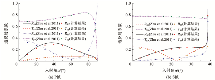
|
图 5 不同入射角下的透反射系数(Kelvin节理) Fig. 5 Transmission and reflection coefficients under different incident angles (Kelvin joint) |
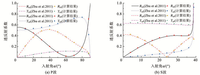
|
图 6 不同入射角下的透反射系数(Maxwell节理) Fig. 6 Transmission and reflection coefficients under different incident angles (Maxwell joint) |
节理模型参数往往通过霍普金森压杆(SHPB)对充填介质进行动态冲击实验的方式获取[12]。但由于SHPB实验中S波难以获得,切向参数的确定存在困难。现假设节理法向与切向同性,即取Kτ1=Kn1,Kτ2=Kn2,Hτ=Hn,除待研究参数外,其余参数同上。设入射波为半个周期的正弦P波或S波,如式(18)所示,Is=Ip。
| $ I_{\mathrm{p}}=\left\{\begin{array}{l} \sin (2 {\rm{ \mathsf{ π} }} f t), t \in[0,1 / 2 f] \\ 0, t \in(1 / 2 f,+\infty) \end{array}\right. $ | (18) |
式中f为正弦波的频率,取1 kHz。
定义法向入射波的能量耗散率为[12]
| $ e_{\text {loss }}=1-\left(R^{2}+T^{2}\right) $ | (19) |
为探究模型参数对透反射系数与能量耗散率的影响,以P波通过单条节理为例,特定刚度系数Kn2分别取为0.2、0.4、0.8和1.6。透反射系数及能量耗散率随1/Kn1和1/Hn的变化曲线分别如图 7、8所示。可以看出,当其他参数为定值时,Kn2对节理模型的影响较为明显,透射系数随着Kn2的增加而增大,而反射系数与能量耗散率均减小。
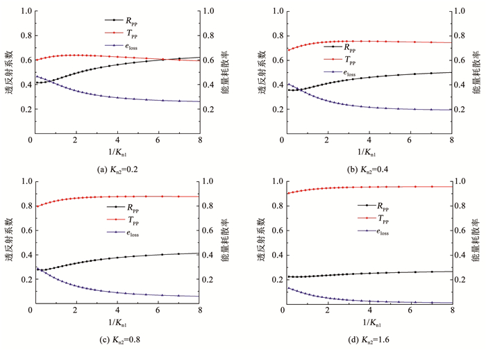
|
图 7 不同Kn2下透反射系数与能量耗散率的变化(Hn=0.5) Fig. 7 Variation of transmission and reflection coefficient and energy dissipation rate with different Kn2 (Hn=0.5) |
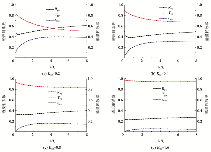
|
图 8 不同Kn2下透反射系数及能量耗散率的变化(Kn1=0.5) Fig. 8 Variation of transmission and reflection coefficient and energy dissipation rate with different Kn2 (Kn1=0.5) |
由图 7可知,当Kn2较小时,随着1/Kn1的增加,反射系数逐渐增加,而透射系数初期有一小段上升,随后缓慢下降;当Kn2较大时,反射和透射系数的初期上升趋势趋弱,且后续随1/Kn1的增大基本持平。能量耗散率随着1/Kn1的增大而逐渐下降,并趋于一定值e0。由于Kn2的增加,模型中Maxwell体的影响逐渐弱化,节理的变形特征由黏弹性逐渐向线弹性演变,因而能量耗散率相应下降。故e0主要由Kn2决定,且随Kn2的增大而减小。
由图 8可知,当Kn2较小时,反射系数初期小幅下降,且下降的趋势随Kn2的增加而逐渐趋缓,但总体随1/Hn增加而上升。同时,透射系数随1/Hn的增加而逐渐下降,且下降幅度随Kn2增加而逐渐减小。能量耗散率eloss随1/Hn的增加逐渐上升,而当1/Hn达2~3之后则基本持平。
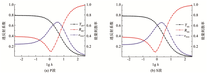
3.2 无量纲节理厚度的影响分析应力波在节理岩体传播的过程中,节理厚度同样会对应力波的传播特性产生影响。考虑到透反射系数的波频依赖性,定义无量纲节理厚度h为ωd/(2πcplate)。图 9为IS和IP法向入射单条节理时透反射系数及能量耗散率随h的变化曲线。可以看出,当S波法向入射时,透反射系数及能量耗散率的大小随lg h的变化趋势与P波法向入射时基本相同。当h < 10-2时,无量纲节理厚度对透反射系数的影响不明显。随着h的增大,透射系数出现明显的下降,并逐渐接近于0。而反射系数随着无量纲节理厚度的增加呈现先降低后增加的现象。此外,随着厚度增加,S波入射时透反射系数的变化趋势要先于P波,而能量耗散率随无量纲节理厚度的增加表现出先上升后下降的趋势。
|
图 9 透反射系数与能量耗散率随无量纲节理厚度的变化 Fig. 9 Variation of transmission and reflection and energy dissipation rate with non-dimensional joint thickness |
取入射S波表达式同P波,图 10、11分别为不同入射角下P波和S波在节理间距为1 m的一组平行等间距节理中传播的透射系数TPP、TPS、TSS和TSP。可以看出,当P波和S波以任意角度入射时,随着节理条数的增加,TPP和TSS均出现了不同程度的下降。在入射P波与S波分别接近临界角αc=90°与βc=arcsin(cs/cp)=38.6°时,TPP和TSS分别出现急剧下降或上升的现象。随着节理条数N的增加,透反射系数在临界角处的“尖点”显著下降,而TPS和TSP随着节理条数的增加而逐渐增大。
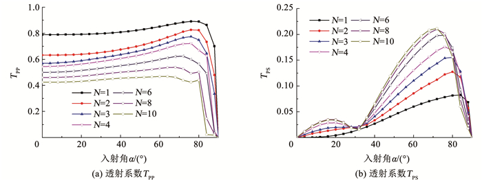
|
图 10 一组平行节理对不同入射角度P波透射系数的影响 Fig. 10 Influence of a set of parallel joints on the transmission coefficients of incident P-wave at different angles |
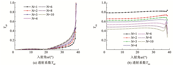
|
图 11 一组平行节理对不同入射角度S波透射系数的影响 Fig. 11 Influence of a set of parallel joints on the transmission coefficients of incident S-wave at different angles |
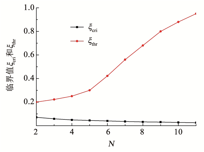
定义无量纲节理间距ξ为节理间距S与入射应力波波长的比值。本节采用半个周期的正弦入射P波,如式(18)所示。图 12为透射系数与无量纲节理间距ξ的关系,易见透射系数随ξ的变化可以分为上升区间(ξ≤ξcri)、下降区间(ξcri < ξ < ξthr)以及不变区间(ξthr≤ξ)。在节理条数较多时,TPP随无量纲节理间距的增加呈线性下降,而黏弹节理则是分为两段——陡峭段和平缓段下降。图 13为临界值ξcri和ξthr随节理数N的变化曲线,可以看出, 随着节理数的增加,临界值ξcri缓慢下降,且基本保持线性关系;对于临界值ξthr,当N<5时,增长较缓;当N>6时,增长较快。
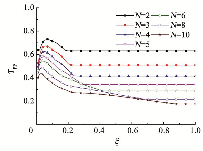
|
图 12 透射系数与无量纲节理间距ξ的关系 Fig. 12 Transmission coefficients versus non-dimensional joint spacing (ξ) |
|
图 13 ξcri和ξthr随节理数N的变化 Fig. 13 Variation of ξcri and ξthr with joint number N |
1) 时域递归方法可用于推导任意角度的入射应力波通过黏弹性节理的传播方程。引入的饱依丁-汤姆逊模型退化为Kelvin模型和Maxwell模型的计算结果不仅验证了所用模型及推导过程的正确性,同时印证了其兼具两种模型的特点,为描述节理复杂的黏弹特性提供了新的模型选择。
2) 参数化研究表明,刚度系数、黏度系数、无量纲节理厚度等都影响透反射系数及能量耗散率。其中,特定刚度系数Kn2与透射系数呈正相关,与反射系数及能量耗散率呈负相关。当无量纲节理厚度小于10-2时,其变化对透反射系数及能量耗散率的影响不明显。
3) 透反射系数随黏弹性节理数及节理间距的变化而变化。对于入射P波(S波),透射P波(S波)随节理数增加而逐渐下降,透射S波(P波)随节理数的增加逐渐上升。当节理条数较少时,节理条数的变化对透射系数影响较大;节理条数较多时,其变化对透射系数的影响则较小。此外,ξcri随节理数的增长基本保持线性关系,但ξthr随节理数的增加呈现先缓后陡的增长趋势。
| [1] |
GOODMAN R E. Methods of geological engineering in discontinuous rocks[M]. Saint Paul: West Publishing Company, 1976.
|
| [2] |
KING M S, MYER L R, REZOWALLI J J. Experimental studies of elastic-wave propagation in a columnar-jointed rock mass[J]. Geophysical Prospecting, 2006, 34(8): 1185. DOI:10.1111/j.1365-2478.1986.tb00522.x |
| [3] |
王志亮, 陈强, 张宇. 黏弹性节理岩体的位移不连续模型研究[J]. 岩土力学, 2015, 36(8): 2177. WANG Zhiliang, CHEN Qiang, ZHANG Yu. A displacement discontinuity model for viscoelastic jointed rock mass[J]. Rock and Soil Mechanics, 2015, 36(8): 2177. DOI:10.16285/j.rsm.2015.08.007 |
| [4] |
LI J C, MA G W. Analysis of blast wave interaction with a rock joint[J]. Rock Mechanicsand Rock Engineering, 2010, 43: 777. DOI:10.1007/s00603-009-0062-0 |
| [5] |
LI J C, MA G W, ZHAO J. Stress wave interaction with a nonlinear and slippery rock joint[J]. International Journal of Rock Mechanics and Mining Sciences, 2011, 48: 493. DOI:10.1016/j.ijrmms.2010.11.013 |
| [6] |
LI J C, LI H B, MA G W, et al. A time-domain recursive method to analyze transient wave propagation across rock joints[J]. Geophysical Journal International, 2012, 188: 631. DOI:10.1111/j.1365-246X.2011.05286.x |
| [7] |
LI J C. Wave propagation across non-linear rock joints based on time-domain recursive method[J]. Geophysical Journal International, 2013, 193(2): 970. DOI:10.1093/gji/ggt020 |
| [8] |
FEHLER M. Interaction of seismic-waves with a viscous-liquid layer[J]. Bulletin of the Seismological Society of America, 1982, 72(1): 55. |
| [9] |
JAEGER J C, COOK N G W, ZIMMERMAN R W. Fundamentals of rock mechanics[M]. Malden: Blackwell Publishing, 2007.
|
| [10] |
HUANG X, QI S, LIU Y, et al. Stress wave propagation through viscous-elastic jointed rock masses using propagator matrix method (PMM)[J]. Geophysical Journal International, 2015, 200(1): 452. DOI:10.1093/gji/ggu407 |
| [11] |
YI W, NIHEI K T, RECTOR J W, et al. Frequency-dependent seismic anisotropy in fractured rock[J]. International Journal of Rock Mechanicsand Mining Sciences, 1997, 34(3/4): 349. DOI:10.1016/s0148-9062(97)00147-2 |
| [12] |
ZHU J B. Seismic response of a single and a set of filled joints of viscoelastic deformational behavior[J]. Geophysical Journal International, 2011, 186: 1315. DOI:10.1111/j.1365-246X.2011.05110.x |
| [13] |
WU W, ZHU J B, ZHAO J. Dynamic response of a rock fracture filled with viscoelastic materials[J]. Engineering Geology Amsterdam, 2013, 160: 1. DOI:10.1016/j.enggeo.2013.03.022 |
| [14] |
LI J C, WU W, LI H B, et al. A thin-layer interface model for wave propagation through filled rock joints[J]. Journal of Applied Geophysics, 2013, 91: 31. DOI:10.1016/j.jappgeo.2013.02.003 |
| [15] |
LI J C, LI H B, JIAO Y Y, et al. Analysis for oblique wave propagation across filled joints based on thin-layer interface model[J]. Journal of Applied Geophysics, 2014, 102: 39. DOI:10.1016/j.jappgeo.2013.11.014 |
| [16] |
LI J C, LIU T T, LI H B, et al. Shear wave propagation across filled Joints with the effect of interfacial shear strength[J]. Rock Mechanics and Rock Engineering, 2015, 48(4): 1547. DOI:10.1007/s00603-014-0662-1 |
| [17] |
ZOU Y, LI J C, LALOUI L, et al. Analytical time-domain solution of plane wave propagation across a viscoelastic rock joint[J]. Rock Mechanics and Rock Engineering, 2017, 50: 2731. DOI:10.1007/s00603-017-1246-7 |
| [18] |
蔡美峰. 岩石力学与工程[M]. 2版. 北京: 科学出版社, 2013: 202. CAI Meifeng. Rock mechanics and engineering[M]. 2nd ed. Beijing: Science Press, 2013: 202. |
| [19] |
WANG R, HU Z P, WANG Q Y. A time-domain recursive method of SH-wave propagation through the filled fracture with linear viscoelastic deformation behavior[J]. Waves in Random and Complex Media, 2019(7): 1014. DOI:10.1080/17455030.2019.1643052 |
| [20] |
ROKHLIN S I, WANG Y J. Analysis of boundary conditions for elastic wave interaction with an interface between two solids[J]. The Journal of the Acoustical Society of America, 1991, 89(2): 503. DOI:10.1121/1.400374 |
| [21] |
DAS B M, RAMANA G V. Principles of soil dynamics[M]. Stamford: Cengage Learning, 2011.
|
| [22] |
VERRUIJT A. An introduction to soil dynamics[M]. Dordrecht: Springer, 2010.
|
| [23] |
SU'AREZ-RIVERA R. The influence of thin clay layers containing liquids on the propagation of shear waves[D]. Berkeley: University of California, 1992
|
 2022, Vol. 54


