微驱动器,也称微执行器或致动器,主要承担着将MEMS(Micro-Electro-Mechanical System)系统的控制信号和电能间接或直接转化为可控运动和功率输出的作用。根据驱动方式的不同,微驱动器主要分为以下几类:静电型、压电型、电磁型及电热型等[1]。电热型驱动器是指在电压作用下由于热膨胀差产生膨胀变形,并最终挤压自由端朝某一方向偏移的一种驱动结构。其本质是导电材料通电由于焦耳热效应产热,从而将电能转化为热能,同时驱动器由于热膨胀效应发生弯曲变形,从而将热能转化为机械能,实现电-热-力之间的能量转换。
微电热驱动器的电-热-力耦合模型对于驱动器的动态响应特性分析及实际应用具有重要的指导意义,也是目前微电热驱动器研究的重点之一。建立U型微电热驱动器的电-热耦合模型途径主要有两种:一种以Huang等[2-5]为代表,通过对驱动器上的微元进行传热分析,基于能量守恒定律和傅里叶导热定律,得到热传导微分或偏微分方程;另一种以Beatriz等[6-9]为代表,将驱动器分割成几个独立的集总热单元,采用等效电路法,建立电-热耦合等效模型。而对于热-力耦合模型,Huang等[2]采用虚力原理对U型微电热驱动器进行受力分析,建立U型微电热驱动器变形协调方程,求解得到驱动器末端位移。Hussein等[10]在此基础上,考虑虚力对驱动器中各梁轴向拉、压的影响,对变形协调方程进行了完善。上述两种构建电-热耦合模型的途径,均未考虑U型电热微驱动器的耦合理论存在材料参数随温度变化及非连续性边界等问题。而针对微驱动器或微运动部件的动态响应测试方法,多采用无接触的光学放大测量技术。陈津平等[11]建立了MEMS驱动器面外运动的全息干涉测量系统,利用Mirau显微干涉技术不断捕获干涉条纹的图像,从而对驱动器的动态位移进行测量, 这种测量方法测量速度快、精度高,但只能用于测量面外运动的位移且经济成本较高。曹云[12]使用高速摄像技术捕捉到了万向惯性开关的闭合过程,并采用亚像素边缘检测算法进行特征提取,测量精度达到了微米级,但没有消除图像噪音对测量可能带来的影响。由此可以看出,基于光学放大测量技术可实现微驱动器微米级别的位移测量,但目前还未有相关文献采用基于边缘检测算法的光学放大测量技术对微电热驱动器的瞬态位移实现可视化测量。
本文首先建立U型微驱动器瞬态位移的电-热-力耦合模型,并通过仿真对其进行验证;然后,搭建基于高速摄像的光学测量系统,结合连续运动目标的图像快速检测算法,实现微电热驱动器瞬态运动的可视化测量;最后,基于搭建的可视化测量系统,对U型微电热驱动器在不同形式电压激励下的瞬态位移特性进行测试分析。本文主要贡献如下:
1) 提出一种全新的电-热耦合模型求解方法,并在建立电-热耦合模型的过程中考虑到了材料参数受温度的非线性影响以及非连续性边界等问题,使得理论模型更加精确。
2) 提出一种基于边缘检测算法的光学放大测量技术,并搭建了测量系统对微电热驱动器的输出位移进行测量,测量误差较小。
3) 探究了在不同形式电压作用下U型微电热驱动器的瞬态位移特性,为微电热驱动器输出位移的可控性研究及其在微光机电系统中的工程应用奠定基础。
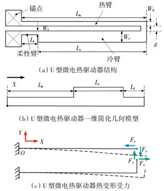
1 U型微电热驱动器的电-热-力耦合模型U型微电热驱动器结构如图 1(a)所示,主要由热臂、冷臂和柔性臂组成,其驱动原理为:在电压作用下,因为热臂电阻大于冷臂电阻,所以热臂总体温度也会高于冷臂,进而导致热臂热膨胀变形远大于冷臂,最终使得U型微电热驱动器末端沿着其冷臂方向弯曲。由于U型微电热驱动器上各臂的长度远大于其宽度和厚度,因此忽略宽度和厚度方向上的热传导,只考虑驱动器长度方向上的热传导,将驱动器沿着热臂水平方向分解为3个串联的线性微束, 由此简化为一维几何模型,如图 1(b)所示。其热变形受力示意图如图 1(c)所示。

|
图 1 驱动器示意图 Fig. 1 Schematic of driver |
驱动器微元传热示意图如图 2所示。

|
图 2 驱动器微元传热示意图 Fig. 2 Schematic diagram of heat transfer in micro-element of the driver |
根据焦耳热效应,微元Δx在通电下产生的焦耳热为
| $ Q_{\mathrm{g}}=J^2 \rho\left(T_m\right) w_m d \Delta x, \quad m=\{\mathrm{h}, \mathrm{c}, \mathrm{f}\} $ | (1) |
式中: m分别代表U型电热驱动器的热臂(h)、冷臂(c)和柔性臂(f);Tm为驱动器各臂的温度;d为驱动器的厚度;wm为驱动器各臂的宽度;ρ为密度;J为电流密度,其表达式为
| $ J=V(t) /\left(\sum\limits_m \int\limits_0^{L_m} \frac{\rho\left(T_m\right)}{w_m d} \mathrm{~d} x\right), m=\{\mathrm{h}, \mathrm{c}, \mathrm{f}\} $ | (2) |
式中V(t)表示驱动器加载电压。
驱动器微元通过热传导方式流入的热量Qin,流出的热量Qout与空气热对流Qouta以及与基地热传导方式损失的热量Qoutd分别为
| $ \begin{cases}Q_{\text {in }}=\kappa\left(T_m\right) w_m d\left[\frac{\partial T}{\partial x}\right]_x, & m=\{\mathrm{h}, \mathrm{c}, \mathrm{f}\} \\ Q_{\text {out }}=\kappa\left(T_m\right) w_m d\left[\frac{\partial T}{\partial x}\right]_{x+\mathrm{d} x}, & m=\{\mathrm{h}, \mathrm{c}, \mathrm{f}\} \\ Q_{\text {outa }}=k\left(T_m-T_0\right)\left(w_m+2 d\right) \Delta x, & m=\{\mathrm{h}, \mathrm{c}, \mathrm{f}\} \\ Q_{\text {outd }}=S_m\left(T_m-T_0\right) w_m \Delta x, & m=\{\mathrm{h}, \mathrm{c}, \mathrm{f}\}\end{cases} $ | (3) |
由热平衡方程
| $ Q_{\mathrm{g}}+Q_{\text {in }}-Q_{\text {out }}-Q_{\text {outa }}-Q_{\text {outd }}=0 $ | (4) |
可得U型微电热驱动器温度分布的瞬态偏微分方程:
| $ \begin{aligned} c \rho_{\mathrm{d}} \frac{\partial T_m}{\partial t}= & \kappa\left(T_m\right) \frac{\partial^2 T_m}{\partial x^2}-k \frac{w_m+2 d}{w_m d}\left(T_m-T_0\right)- \\ & \frac{S_m}{d}\left(T_m-T_0\right)+J^2 \frac{\rho\left(T_m\right)}{w_m d}, m=\{\mathrm{h}, \mathrm{c}, \mathrm{f}\} \end{aligned} $ | (5) |
式中: k为驱动器与空气热对流系数,这里k取70 W/(m2·K);Sm为驱动器各臂与基底间的传热系数;由于驱动器与基底间距只有数十微米,该传热强度介于热传导与热对流之间,由文献[13]计算得Sh、Sc和Sf分别取5 500、400和5 500 W/(m2·K),T0为室温。
图 1(b)所示的一维模型存在两个间断点,分别为热臂与冷臂的连接处以及冷臂与柔性臂的连接处,间断点处的温度二阶可导,即温度和温度的一阶导数在间断点处具有连续性。
假设驱动器边界处的温度始终等于室温,且瞬态偏微分方程的初始时刻条件如下:
| $ T_m(x, 0)=T_0, m=\{\mathrm{h}, \mathrm{c}, \mathrm{f}\} $ | (6) |
代入式(5)可进一步化简得
| $ \begin{aligned} c \rho_{\mathrm{d}} \frac{\partial u_m}{\partial t}= & \kappa\left(u_m\right) \frac{\partial^2 u_m}{\partial x^2}-k \frac{w_m+2 d}{w_m d} u_m- \\ & \frac{S_m}{d} u_m+J^2 \frac{\rho\left(u_m\right)}{w_m d}, m=\{\mathrm{h}, \mathrm{c}, \mathrm{f}\} \end{aligned} $ | (7) |
式中:u表示绝对温度,即实际温度T与室温T0之差。
U型微电热驱动器的边界条件和初始时刻条件分别为
| $ \begin{cases}u_{\mathrm{h}}\left(x_0, t\right)=0, & x_0=0 \\ u_{\mathrm{f}}\left(x_0, t\right)=0, & x_0=L_{\mathrm{h}}+L_{\mathrm{c}}+L_{\mathrm{f}}\end{cases} $ | (8) |
| $ u_m(x, 0)=0, m=\{\mathrm{h}, \mathrm{c}, \mathrm{f}\} $ | (9) |
采用切比雪夫谱方法对方程组(7)中的每个偏微分方程的空间域逐个进行处理。首先在区间[0, Lh]、[Lh, Lh+Lc]和[Lh+Lc, Lh+Lc+Lf]分别选取Nh+1、Nc+1和Nf+1个切比雪夫点,可依次用向量xh、xc和xf表示。每个区间内,切比雪夫点处的绝对温度向量分别为uh、uc和uf。得到绝对温度关于位置二阶偏导数的切比雪夫求导矩阵分别为D2Nh、D2Nc和D2Nf。
在方程组(6)中对温度关于时间的偏导数采用欧拉前向差分法进行时域离散,可得
| $ \left(\boldsymbol{u}_m\right)^{n+1}=\hat{\boldsymbol{D}}_{N_m}^2\left(\boldsymbol{u}_m\right)^n+f\left(\boldsymbol{x}_m\right), m=\{\mathrm{h}, \mathrm{c}, \mathrm{f}\} $ | (10) |
其中:
| $ \begin{aligned} & \left(\hat{\boldsymbol{D}}_{N_m}^2\right)_{i j}= \\ & \left\{\begin{array}{l} \frac{\Delta t}{c \rho_{\mathrm{d}}}\left[\boldsymbol{\kappa}\left(\left(u_m\right)_j^{g(n)}\right)\left(\boldsymbol{D}_{N_m}^2\right)_{i j}-\right. \\ \left.\quad\left(k \frac{w_m+2 d}{w_m d}+\frac{S_m}{d}\right)\right]+1, \quad i=j \\ \frac{\kappa\left(\left(u_m\right)_j^{g(n)}\right) \Delta t}{c \rho_{\mathrm{d}}}\left(\boldsymbol{D}_{N_m}^2\right)_{i j}, \quad i \neq j, \text { 且 } i, j=0, 1, \cdots, N_m \end{array}\right. \end{aligned} $ | (11) |
| $ f\left(\boldsymbol{x}_m\right)_j=\frac{\Delta t J^2 \rho_0\left(1+\gamma\left(\left(u_m\right)_j^{g(n)}\right)\right)}{c \rho_{\mathrm{d}} \kappa\left(\left(u_m\right)_j^{g(n)}\right)}, m=\{\mathrm{h}, \mathrm{c}, \mathrm{f}\} $ | (12) |
式中: Δt为求解时间步长,n为时间步序号,g(n)为材料参数更新函数, 且g(n)=[n/ns]n。
采用差分法对空间域中的间断点处所满足的方程进行离散,有
| $ \left\{\begin{array}{l} \left(\boldsymbol{u}_{\mathrm{c}}\right)_0^{n+1}=f c_1\left(\boldsymbol{u}_{\mathrm{f}}\right)_{N_{\mathrm{f}}-1}^{n+1}+f c_2\left(\boldsymbol{u}_{\mathrm{c}}\right)_1^{n+1} \\ \left(\boldsymbol{u}_{\mathrm{h}}\right)_0^{n+1}=\operatorname{ch}_1\left(\boldsymbol{u}_{\mathrm{c}}\right)_{N_{\mathrm{c}}-1}^{n+1}+c h_2\left(\boldsymbol{x}_{\mathrm{h}}\right)_1^{n+1} \end{array}\right. $ | (13) |
其中:
| $ \left\{\begin{array}{l} f c_1=\frac{w_{\mathrm{f}}\left[\left(\boldsymbol{x}_{\mathrm{c}}\right)_0^{n+1}-\left(\boldsymbol{x}_{\mathrm{c}}\right)_1^{n+1}\right]}{w_{\mathrm{f}}\left[\left(\boldsymbol{x}_{\mathrm{c}}\right)_0^{n+1}-\left(\boldsymbol{x}_{\mathrm{c}}\right)_1^{n+1}\right]+w_{\mathrm{c}}\left[\left(\boldsymbol{x}_{\mathrm{f}}\right)_{N_{\mathrm{f}}-1}^{n+1}-\left(\boldsymbol{x}_{\mathrm{f}}\right)_{N_{\mathrm{f}}}^{n+1}\right]} \\ f c_2=1-f c_1 \\ c h_1=\frac{w_{\mathrm{c}}\left[\left(\boldsymbol{x}_{\mathrm{h}}\right)_0^{n+1}-\left(\boldsymbol{x}_{\mathrm{h}}\right)_1^{n+1}\right]}{w_{\mathrm{c}}\left[\left(\boldsymbol{x}_{\mathrm{h}}\right)_0^{n+1}-\left(\boldsymbol{x}_{\mathrm{h}}\right)_1^{n+1}\right]+w_{\mathrm{h}}\left[\left(\boldsymbol{x}_{\mathrm{c}}\right)_{N_{\mathrm{c}}-1}^{n+1}-\left(\boldsymbol{x}_{\mathrm{c}}\right)_{N_{\mathrm{c}}}^{n+1}\right]} \\ c h_2=1-c h_1 \end{array}\right. $ | (14) |
得到瞬态模型求解矩阵方程如图 3所示。

|
图 3 U型电热驱动器瞬态模型求解矩阵方程 Fig. 3 Solving matrix equation of transient model of U-shaped electrothermal actuator |
因为U型微电热驱动器冷臂末端的弯曲变形最大,所以将此处的挠度视为驱动器的位移。将驱动器视为超静定杆结构,根据虚功原理,在不考虑热变形并去除热臂与冷臂连接处约束的情况下,假设驱动器热臂与冷臂连接处存在相互作用力,驱动器冷臂与热臂间的变形差等于其在热应力作用下的变形差,则通过该相互作用力计算得到的驱动器位移为热应力作用下的位移。驱动器受力情况如图 1(c)所示。
结合电-热耦合分析得到的温度分布,U型电热驱动器上各臂的热膨胀变形为
| $ \begin{gathered} \Delta {l_m} = \sum\limits_m {\left( {\sum\limits_{i = 1}^{{N_m} - 1} {\left( {\left( {{x_{i + 1}} - {x_{i - 1}}} \right)\int\limits_{{T_0}}^{{T_m}\left( {{x_i}} \right)} \alpha (T){\text{d}}T} \right)} /2} \right)} \hfill \\ m = \{ {\text{h}}, {\text{c}}, {\text{f}}\} \hfill \\ \end{gathered} $ | (15) |
热臂与其他两臂的热膨胀变形差Δld为
| $ \Delta l_{\mathrm{d}}=\Delta l_{\mathrm{h}}-\Delta l_{\mathrm{c}}-\Delta l_{\mathrm{f}} $ | (16) |
轴向力Fx对柔性臂和冷臂作用的力矩Mx为
| $ M_x=F_x\left(g+\left(W_{\mathrm{h}}+W_{\mathrm{f}}\right) / 2\right) $ | (17) |
式中g为热臂与冷臂之间的间隙宽度。
力Fx对热臂轴向压缩的变形量为
| $ \delta_{\mathrm{h} x}=F_x L_{\mathrm{h}} /\left(E W_{\mathrm{h}} d\right) $ | (18) |
设ω和θ为某一作用力作用下某臂所产生的挠度和转角以及相对位移和相对转角,根据材料力学梁弯曲变形理论[14]以及多段刚度法[15],有
| $ \left\{\begin{array}{l} \omega_{\mathrm{fy}}=F_y L_{\mathrm{f}}^3 / 3 E I_{\mathrm{f}}, \theta_{\mathrm{fy}}=F_y L_{\mathrm{f}}^2 / 2 E I_{\mathrm{f}} \\ \omega_{\mathrm{c} 0}=\theta_{\mathrm{fy}} L_{\mathrm{c}}+F_y L_{\mathrm{c}}^3 /\left(3 E I_c\right), \theta_{\mathrm{cy} 0}=F_y L_{\mathrm{c}}^2 /\left(2 E I_{\mathrm{c}}\right) \\ \omega_{\mathrm{hy}}=F_y L_{\mathrm{h}}^3 /\left(3 E I_{\mathrm{h}}\right), \theta_{\mathrm{h} y}=F_y L_{\mathrm{h}}^2 /\left(2 E I_{\mathrm{h}}\right) \\ \omega_{\mathrm{f} x}=M_x L_{\mathrm{f}}^2 /\left(2 E I_{\mathrm{f}}\right), \theta_{\mathrm{f} x}=M_x L_{\mathrm{f}} /\left(E I_{\mathrm{f}}\right) \\ \omega_{\mathrm{cx} 0}=\theta_{\mathrm{f} x} L_{\mathrm{c}}+M_x L_{\mathrm{c}}^2 /\left(2 E I_{\mathrm{c}}\right), \theta_{\mathrm{cx} 0}=M_x L_{\mathrm{c}} /\left(E I_{\mathrm{c}}\right) \end{array}\right. $ | (19) |
式中:Im是各臂的惯性矩,
在Fy作用下冷臂和Fx作用下冷臂末端总的弯曲挠度和转角分别为
| $ \left\{\begin{array}{l} \omega_{\mathrm{cm}}=\omega_{\mathrm{f} m}+\omega_{\mathrm{cm} 0} \\ \theta_{\mathrm{cm}}=\theta_{\mathrm{f} m}+\theta_{\mathrm{cm} 0} \end{array} \quad m=\{x, y\}\right. $ | (20) |
根据压缩和弯曲变形以及热膨胀变形差Δld,热臂末端的位置(Hx, Hy)为
| $ \left\{\begin{array}{l} H_x=L_{\mathrm{h}}-\omega_{\mathrm{h} y} \sin \left(\theta_{\mathrm{h} y}\right)+\left(\Delta l_{\mathrm{d}}-\delta_{\mathrm{h} x}\right) \cos \left(\theta_{\mathrm{h} y}\right) \\ H_y=-\omega_{\mathrm{hy}}-\left(\Delta l_{\mathrm{d}}-\delta_{\mathrm{h} x}\right) \sin \left(\theta_{\mathrm{h} y}\right) \end{array}\right. $ | (21) |
在力矩Mx和力Fy作用下,驱动器变形后的冷臂末端位置(Cx, Cy)为
| $ \left\{\begin{array}{l} C_x=L_c+\left(g-\omega_{c x}\right) \sin \left(\theta_{c x}-\theta_{c y}\right) \\ C_y=-g-\omega_{c x}+\omega_{c y}+g \cos \left(\theta_{c x}-\theta_{c y}\right) \end{array}\right. $ | (22) |
根据超静定结构原理得到非线性方程组为
| $ \left\{\begin{array}{l} H_x=C_x \\ H_y=C_y \end{array}\right. $ | (23) |
由此可得驱动器的位移为
| $ S=\omega_{\mathrm{f} x}+\omega_{c x 0}-\omega_{\mathrm{f} y}-\omega_{\mathrm{c} y 0} $ | (24) |
本文所研究的微电热驱动器的结构尺寸如表 1所示。
| 表 1 U型微电热驱动器结构参数 Tab. 1 Structural parameters of the U-shaped micro-electrothermal actuator |
微电热驱动器的材料均为高浓度P型掺杂单晶硅,表 2给出了室温下单晶硅的热学和力学材料参数。
| 表 2 室温下单晶硅的热学和力学材料参数 Tab. 2 Thermal and mechanical material parameters of single crystal silicon at room temperature |
单晶硅的部分材料性质会随着温度的升高而发生显著的变化,其导热系数、电阻率和热膨胀系数与温度T关系的拟合公式分别如下[16]:
| $ \left\{\begin{array}{l} \kappa(T)=210658 T^{-1.2747} \\ \rho(T)=\rho_0(1+\gamma(T-273)), \gamma=3 \times 10^{-3} \\ \alpha(T)=-4 \times 10^{-12} T^2+8 \times 10^{-9} T+4 \times 10^{-7} \end{array}\right. $ | (25) |
根据上述数据在ANSYS软件内建立U型微电热驱动器有限元分析模型,如图 4所示。假设: 锚点下底面温度始终等于室温;另一方面,对锚点下底面施加固定位移条件(0 m);在两锚点的顶面分别施加电势条件(16 V)和(0 V);对驱动器热臂与柔性臂的底面、冷臂的底面和驱动器的剩余面施加热对流条件,热对流系数分别为Sh、Sc和k。

|
图 4 U型电热驱动器三维几何模型 Fig. 4 Three-dimensional geometric model of U-shaped electrothermal actuator |
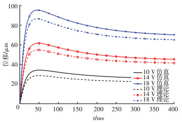
在14 V和18 V电压作用下,U型电热驱动器的瞬态位移理论计算与仿真结果如图 5所示。可以看出U型电热驱动器的理论瞬态位移和仿真瞬态位移总体吻合较好,验证了构建的电-热-力耦合模型的正确性;但在曲线峰值处的相差较大,且随着加载电压的增加,该处的偏差也逐渐增大。

|
图 5 不同电压情况下驱动器的理论与仿真瞬态位移 Fig. 5 Theoretical and simulated transient displacement of the driver under different voltages |
采用基于高速摄影的MEMS结构动态测试技术,搭建微电热驱动器高速光学动态测量系统,如图 6所示。

|
图 6 微电热驱动器高速光学动态测量系统 Fig. 6 High-speed optical dynamic measurement system of electrothermal actuator |
将显微镜聚焦于U型微电热驱动器的冷臂末端,并对其进行放大,再将高速摄像机对准显微镜目镜,为保证拍摄过程中有足够的光照强度,将光源完全对着镜筒照明。
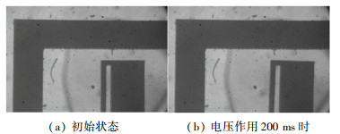
2.2 驱动器位置特征提取方法单独采用Canny算子[17]对图像进行边缘检测时,背景部分的噪声较大,所以采用了差分与Canny算子融合边缘检测算法。微电热驱动器图像处理流程如图 7所示。图 7中,在不考虑尺寸误差的情况下,驱动器运动所扫过的区域接近于矩形。差分与Canny算子融合边缘检测算法的精度为像素级,能够精确地检测出边缘点位于某个像素点内,但不能精确得知图像边缘位于像素点的具体位置。测量误差需要对图像标尺(边框)进行计算,从而得到图像中一个像素点的长度,经计算可知误差通常<4 μm。光学测量结果和边缘检测结果分别如图 8和图 9所示。

|
图 7 差分与Canny算子融合边缘检测算法下微电热驱动器图像处理流程 Fig. 7 Image processing flow of micro-electrothermal driver based on differential and Canny operator fusion edge detection algorithm |

|
图 8 恒定电压作用下U型微电热驱动器冷臂末端的高速光学测量结果 Fig. 8 High-speed optical measurement results of the cold arm end of the U-shaped micro-electrothermal actuator under constant voltage |

|
图 9 恒定电压作用下U型微电热驱动器冷臂末端扫过区域边缘检测结果 Fig. 9 Detection results of the edge of the swept area produced by the cold arm end of the U-shaped micro-electrothermal actuator under constant voltage |
在14 V和18 V电压作用下U型微电热驱动器瞬态位移理论、仿真和实验曲线如图 10所示。由图 10可以看出,理论、仿真曲线与实验动态位移曲线三者的变化趋势基本一致。在恒定电压的作用下,驱动器位移迅速达到最大值,此后位移出现微小的减小并逐渐趋于稳定。这是因为U型微电热驱动器的冷臂与热臂的温差很大,在热臂迅速到达稳态时,冷臂仍然继续从热臂吸热升温并逐渐到达稳态。期间,热臂和冷臂的变形差会不断减小,造成位移在达到最大值后也会不断减小,即出现位移回落现象。随着电压的增大,U型微电热驱动器位移达到最大值的时间越短,回落现象也越明显。由于理论建模和仿真分析中没有考虑冷热臂间空气间隙换热的影响,而在14 V电压作用下,热臂温度相对较低,可借助空气间隙的换热较快达到稳定状态,因此位移回落现象不明显;而在18 V电压作用下,空气间隙换热对热臂温度下降的影响较小,因此位移回落现象相对明显。

|
图 10 不同电压下驱动器理论、仿真和实验瞬态位移对比图 Fig. 10 Comparison of theoretical, simulated, and experimental transient displacement of the driver under different voltages |
U型微电热驱动器在频率为50 Hz、峰峰值为16 V、偏置为+8 V和峰峰值为8 V、偏置为+12 V的两种正弦电压作用下,前10个周期中电压相位为0°和90°时的位移与在第13、14个周期中的位移如图 11所示。在图 11(a)中,随着周期的增加,同一电压相位处的驱动器位移逐渐增加,并最终到达稳定状态;峰峰值16 V电压下,驱动器位移的峰峰值约为20 μm,而峰峰值8 V电压下,驱动器位移的峰峰值约为10 μm。从图 11(b)中可以看出,在正弦偏置电压作用下,U型微电热驱动器的位移最终也类似于正弦变化,且运动周期与电压变化周期相等;等效电压值越大,驱动器的位移均值越大。

|
图 11 频率为50 Hz正弦电压作用下驱动器的位移变化曲线 Fig. 11 Displacement curves of the driver applied by 50 Hz sinusoidal voltage |
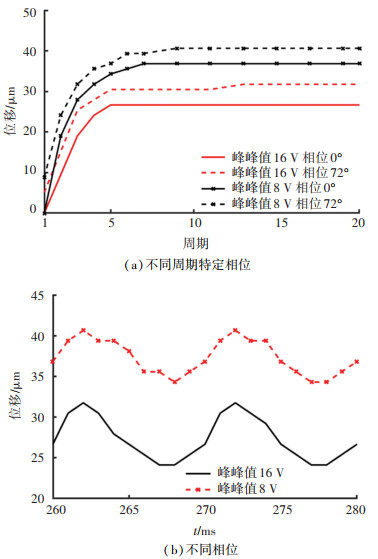
在频率为100 Hz、峰峰值为16 V、偏置为+8 V和峰峰值为8 V、偏置为+12 V的两种正弦电压作用下,前20个周期中电压相位为0°和72°时的位移与在第26、27个周期中的位移如图 12所示。由图 12可知, 随着频率的增加,U型微电热驱动器的位移变化幅度逐渐减小,但位移均值不变。

|
图 12 频率为100 Hz正弦电压作用下驱动器的位移变化曲线 Fig. 12 Displacement curves of the driver applied by 100 Hz sinusoidal voltage |
1) 建立了U型电热微驱动器的电热耦合模型以及热力耦合模型,并与仿真和实验结果进行对比。不同加载电压下,通过理论模型得到的驱动器稳态位移与仿真、实验结果基本相符,但由于无法准确获得导热系数、对流系数等热耗散系数值与温度之间的关系,在电压加载初始阶段,由于采用的热耗散系数大于实际值,驱动器温度升高较慢,从而导致理论和仿真位移的增加较慢。
2) 搭建了高速光学动态测量系统平台,采用差分与Canny算子融合的边缘检测算法,实现了微电热驱动器动态特性的测量,U型微电热驱动器在恒定电压作用下的位移响应测量结果与理论和仿真结果对比表明,测量系统测量结果较为可靠。
3) 在正弦电压作用下,在前几个周期内(非稳定状态下)位移随时间逐渐增大,与稳态电压作用时情况较为相似;稳定状态下微电热驱动器位移变化趋势同样呈现正弦规律变化,且变化周期与电压周期相等;随着电压峰峰值的减小以及频率的增加,微电热驱动器的位移变化幅度逐渐减小,但位移均值不变。
| [1] |
解甜, 王传礼, 喻曹丰. 关于新型功能材料精密微驱动器的研究综述[J]. 微电机, 2019, 52(7): 72. XIE Tian, WANG Chuanli, YU Caofeng. Research review on precision micro-actuators with new functional materials[J]. Micromotor, 2019, 52(7): 72. DOI:10.3969/j.issn.1001-6848.2019.07.014 |
| [2] |
HUANG Qingan, LEE N K S. Analysis and design of polysilicon thermal flexure actuator[J]. Journal of Micromechanics & Microengineering, 1999, 9(1): 64. DOI:10.1088/0960-1317/9/1/308 |
| [3] |
KUANG Yining, HUANG Qingan, LEE N. Numerical simulation of a polysilicon thermal flexure actuator[J]. Microsystem Technologies, 2002, 8(1): 17. DOI:10.1007/s00542-002-0096-7 |
| [4] |
ZHANG Yuxing, HUANG Qingan, LI Rengang, et al. Macro-modeling for polysilicon cascaded bent beam electrothermal microactuators[J]. Energy Harvesting & Systems, 2015, 128(1): 165. DOI:10.1016/j.sna.2005.12.033 |
| [5] |
MAYYAS M, SHIAKOLAS P S, LEE W H, et al. Thermal cycle modeling of electrothermal microactuators[J]. Sensors & Actuators A Physical, 2009, 152(2): 192. DOI:10.1016/j.sna.2009.03.015 |
| [6] |
BEATRIZ L W, MICHAËL G, NICOLAS C. Dynamic modelling for thermal micro-actuators using thermal networks[J]. International Journal of Thermal Sciences, 2010, 49(11): 2108. DOI:10.1016/j.ijthermalsci.2010.06.012 |
| [7] |
BAKRI-KASSEM M, DHAOUADI R, ARABI M, et al. Nonlinear dynamic modeling of a V-shaped metal based thermally driven MEMS actuator for RF switches[J]. Journal of Micromechanics and Microengineering, 2018, 28(5): 054004. DOI:10.1088/1361-6439/aaafb2 |
| [8] |
ESTAHBANATI S V, DHAOUADI R, BAKRI-KASSEM M. Macromodeling of thermally driven V-shaped MEMS actuators[J]. Mechatronics, 2017, 46: 193. DOI:10.1016/j.mechatronics.2017.03.006 |
| [9] |
DZUNG N T, PHUC P H, DICH N Q, et al. Iterative learning control for V-shaped electrothermal microactuator[J]. Electronics, 2019, 8(12): 1410. DOI:10.3390/electronics8121410 |
| [10] |
HUSSEIN H, TAHHAN A, MOAL P L, et al. Dynamic electro-thermo-mechanical modeling of a U-shaped electrothermal actuator[J]. Journal of Micromechanics & Microengineering, 2016, 26(2): 025010. DOI:10.1088/0960-1317/26/2/025010 |
| [11] |
陈津平, 郭彤, 胡春光, 等. 基于时间平均干涉法的微结构离面运动测量[J]. 天津大学学报, 2006, 39(增刊): 125. CHEN Jinping, GUO Tong, HU Chunguang, et al. Measurement of off-plane motion of microstructures based on time-averaged interferometry[J]. Journal of Tianjin University, 2006, 39(S1): 125. DOI:10.3969/j.issn.0493-2137.2006.z1.024 |
| [12] |
曹云. 非硅MEMS万向惯性开关设计与动态可视化测试方法研究[D]. 南京: 南京理工大学, 2017 CAO Yun. Research on the design and dynamic visual test method of non-silicon MEMS universal inertial switch[D]. Nanjing: Nanjing University of Science and Technology, 2017 |
| [13] |
HICKEY R, SAMEOTO D, HUBBARD T, et al. Time and frequency response of two-arm micromachined thermal actuators[J]. Journal of Micromechanics & Microengineering, 2002, 13(1): 40. DOI:10.1088/0960-1317/13/1/306 |
| [14] |
苏振超. 材料力学[M]. 北京: 清华大学出版社, 2016. SU Zhenchao. Mechanics of materials[M]. Beijing: Tsinghua University Press, 2016. |
| [15] |
苑学众, 刘杰民. 变截面悬臂梁的刚度叠加法[J]. 力学与实践, 2011, 33(2): 89. YUAN Xuezhong, LIU Jiemin. Stiffness superposition method of variable cross-section cantilever beam[J]. Mechanics in Engineering, 2011, 33(2): 89. DOI:10.6052/1000-0992-lxysj2009-446 |
| [16] |
CHANG T H, ZHU Yong. A microelectromechanical system for thermomechanical testing of nanostructures[J]. Applied Physics Letters, 2013, 103(26): 263114. DOI:10.1063/1.4858962 |
| [17] |
赵小川. MATLAB图像处理[M]. 北京: 北京航空航天大学出版社, 2014. ZHAO Xiaochuan. MATLAB image processing[M]. Beijing: Beijing University of Aeronautics and Astronautics Press, 2014. |
 2023, Vol. 55


