2. 航空动力装备振动及控制教育部重点试验室(东北大学), 沈阳 110819
2. Key Laboratory of Vibration and Control of Aerodynamic Equipment (Northeastern University, Shenyang), Ministry of Education, Shenyang 110819, China
叶片是航空发动机的核心部件之一,在航空工业中得到了广泛的应用。由于叶片长期受到交变载荷激励的影响,极易诱发叶片振动并引发高周疲劳,进而导致叶片出现裂纹,改变结构的性能及工作稳定性。因此,研究旋转裂纹叶片的振动特性对提高叶片的可靠性及裂纹故障诊断具有重要的工程意义。
在过去的几十年里,叶片振动得到了大量的研究[1-2],提出了集中质量模型[3]、半解析模型[4-6]与有限元模型[7-8]等。为了模拟裂纹面在振动过程中出现的呼吸现象,部分学者提出了双线性裂纹模型[9-11]。由于离心应力和弯曲应力的共同作用,裂纹除了存在打开与闭合两种状态外,还存在部分开启状态。因此,Zeng等[12]采用接触有限元对升速过程的压气机旋转裂纹叶片动力学特性进行了研究。Xie等[13]考虑拉应力与弯曲应力的影响,提出了一种基于应力来模拟旋转裂纹叶片裂纹面间呼吸效应的建模方法。Long等[14]采用傅里叶级数模拟裂纹面间的呼吸效应,对裂纹叶片的非线性特性进行了研究。Zhang等[15]基于开闭裂纹面的面积提出了含呼吸效应的穿透裂纹叶片动力学模型。上述研究中,大多是基于弹簧、接触单元等对裂纹叶片的呼吸效应进行模拟的,这些呼吸模型难以表征裂纹面接触区域的变化情况。
在实际工作环境中,由于叶片经常受到气流激振力、离心力等综合影响,裂纹形式不仅仅表现为直裂纹,还存在斜裂纹的情况,如图 1所示。目前大部分学者只针对矩形截面悬臂梁以及轴受扭转产生的斜裂纹进行了研究[16-17]。Ma等[18]基于平面单元与梁单元建立了斜裂纹悬臂梁的有限元模型,分析了不同裂纹参数及载荷参数对斜裂纹悬臂梁动力学特性的影响。Liu等[19]对含斜裂纹转轴的动力学特性进行了研究。Ma等[20]采用三角插值函数模拟斜裂纹悬臂梁的刚度变化,并指出斜裂纹角度也是影响裂纹悬臂梁固有特性的因素之一。综上所述可知,目前很少有研究考虑裂纹角度对叶片固有特性与响应特性的影响。

|
图 1 斜裂纹示意 Fig. 1 Schematic of slant crack |
上述文献调查表明,很少有学者建立含呼吸效应的斜裂纹扭形旋转叶片的动力学模型。因此,本文首先推导了新的含斜裂纹梁单元的应力强度因子与柔度矩阵,提出了一种根据斜裂纹面接触区域来计算斜裂纹梁单元时变刚度的方法,建立了含呼吸效应的旋转斜裂纹扭形叶片的动力学模型;其次,通过与ANSYS有限元模型对比验证了本文模型的有效性;最后,讨论了裂纹叶片在超谐共振状态与第1阶共振状态下,不同裂纹角度对裂纹叶片振动特性的影响。
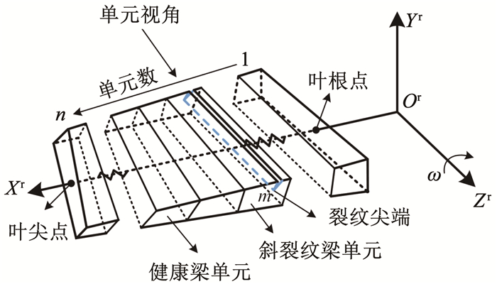
1 含呼吸效应的斜裂纹旋转叶片动力学模型含斜裂纹的旋转扭形叶片模型如图 2所示,其中,OXYZ为固定坐标系,OrXrYrZr为旋转坐标系,oxyz为叶片任意一个截面的局部坐标系。L为裂纹叶片的长度,Lc为叶片根部与裂纹尖端的距离,B为叶根处叶片宽度,H为叶根处叶片厚度。扭形斜裂纹叶片在旋转坐标系OrXrYrZr中绕OrZr轴旋转,Rd为轮盘半径,ω为叶片旋转角速度。h、b分别为叶片任意横截面处的厚度和宽度,其中,h=(1-τhx/L)H,b=(1-τbx/L)B。

|
图 2 旋转扭形斜裂纹叶片结构图 Fig. 2 Structural diagram of rotating twisted slant crack blade |
在本文中,将扭形叶片分为健康与含裂纹区域两部分,其中,健康部分扭形叶片采用Timoshenko梁单元来建立,Timoshenko梁单元第k个单元的质量矩阵、刚度矩阵、陀螺矩阵、旋转软化矩阵、离心刚化矩阵等详见文献[23]。
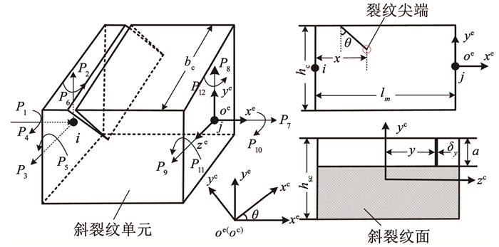
1.1 斜裂纹梁单元模型如图 3所示为含斜裂纹单元的扭形叶片示意图。图 4所示为叶片斜裂纹梁单元示意图,oexeyeze为斜裂纹单元坐标系,ocxcyczc为斜裂纹面坐标系,其中,斜裂纹面坐标系为斜裂纹单元坐标系绕oeze轴旋转θ角而成。bc为裂纹单元的宽度,hc为裂纹单元的高度,lm为裂纹单元的长度,a为斜裂纹上的裂纹深度,斜裂纹面的高度为hsc=hc/cos θ,x为裂纹尖端距左节点i的距离。对于斜裂纹梁单元,其受轴向拉力P1与P7,剪切力P2、P3、P8与P9,扭矩P4与P10,弯矩P5、P6、P11与P12。

|
图 3 含斜裂纹的旋转扭形叶片示意 Fig. 3 Schematic of rotating twisted blade with slant crack |

|
图 4 斜裂纹梁单元示意 Fig. 4 Schematic of slant crack beam element |
在断裂力学中,按照力学特性可将裂纹形式划分为:Ⅰ型(张开型)裂纹、Ⅱ型(滑开型)裂纹、Ⅲ型(撕开型)裂纹。针对这3种不同的裂纹形态,将其对应的应力强度因子分别记为:KⅠ、KⅡ与KⅢ。对于实际的裂纹体,由于裂纹产生的应力集中使得裂纹尖端的应力强度因子比理论值大,因此,考虑应力集中的影响,将Ki(i=Ⅰ、Ⅱ、Ⅲ)的表达式记为
| $ K_i=\sigma_i \sqrt{\pi a} \cdot F_i(\gamma) $ | (1) |
式中:σi、Fi(γ)(i=1, 2, 3)分别为无裂纹体的应力和应力强度因子修正系数[16],其中γ为裂纹深度比,γ=a/hsc。
由Castigliano定理[16]可知,裂纹深度为a所引起的附加广义位移μi为
| $ \mu_i=\frac{\partial U}{\partial P_i} $ | (2) |
式中:Pi、U分别为相应的载荷和总的应变能,总应变能为无裂纹单元的应变能与裂纹单元应变能的总和,即[16]
| $ \left\{\begin{aligned} U= & U^{\mathrm{n}}+U^{\mathrm{c}} \\ U^{\mathrm{n}}= & \frac{1}{2} \int\left[\frac{P_1^2}{E A_x}+\frac{\kappa P_2^2}{G A_x}+\frac{\kappa P_3^2}{G A_x}+\frac{P_4^2}{G\left(I_z+I_y\right)}+\right. \\ & \left.\frac{\left(P_5+x P_3\right)^2}{E I_y}+\frac{\left(x P_2-P_6\right)^2}{E I_z}\right] \mathrm{d} x \\ U^{\mathrm{e}}= & \iint\limits_{A_{\mathrm{c}}} \frac{1-v^2}{E}\left[\left(\sum\limits_{r=1}^6 K_{\mathrm{I}r}\right)^2+\left(\sum\limits_{r=1}^6 K_{\mathrm{II} r}\right)^2+\right. \\ & \left.(1+v)\left(\sum\limits_{r=1}^6 K_{\mathrm{IIIr}}\right)^2\right] \mathrm{d} A_{\mathrm{c}} \end{aligned}\right. $ | (3) |
式中:Un、Uc分别为无裂纹梁单元的应变能和由结构裂纹扩展产生的附加应变能。
进一步可得到柔度矩阵系数为[24]
| $ \left\{\begin{array}{l} \boldsymbol{g}_{i j}=\boldsymbol{g}_{i j}^{\mathrm{n}}+\boldsymbol{g}_{i j}^{\mathrm{c}} \\ \boldsymbol{g}_{i j}=\frac{\partial^2 U^{\mathrm{n}}}{\partial P_i \partial P_j}+\frac{\partial^2 U^{\mathrm{c}}}{\partial P_i \partial P_j}(i, j=1, \cdots, 6) \end{array}\right. $ | (4) |
式中:gijn、gijc分别为单元体无裂纹时的柔度矩阵和由裂纹扩展引起的柔度矩阵。
当结构中的裂纹存在一个角度时,传统的直裂纹应力强度因子已不再适用。因此,考虑裂纹角度的影响,结合图 4与式(1),本文重新推导了斜裂纹尖端的应力强度因子:
| $ \begin{array}{l} \left\{\begin{array}{l} K_{\mathrm{I} 1}=\frac{P_1 \cos \theta}{A_{\mathrm{c}}} \sqrt{\pi a} F_1(\gamma) \\ K_{\mathrm{I} 2}=\frac{\kappa P_2 \sin \theta}{A_{\mathrm{c}}} \sqrt{\pi a} F_1(\gamma) \\ K_{\mathrm{I} 3}=0 \\ K_{\mathrm{I} 4}=0 \\ K_{\mathrm{I} 5}=\frac{y\left(P_5+x P_3\right) \cos \theta}{I_{y \mathrm{c}}} \sqrt{\pi a} F_1(\gamma) \\ K_{\mathrm{I6}}=\frac{\left(x P_2-P_6\right) h_{\mathrm{c}} / \cos \theta}{2 I_{z c}} \sqrt{\pi a} F_2(\gamma) \end{array}\right.\\ \left\{\begin{array}{l} K_{\mathrm{II} 1}=\frac{-P_1 \sin \theta}{A_{\mathrm{c}}} \sqrt{\pi a} F_{\mathrm{II}}(\gamma) \\ K_{\mathrm{II} 2}=\frac{\kappa P_2 \cos \theta}{A_{\mathrm{c}}} \sqrt{\pi a} F_{\mathrm{II}}(\gamma) \\ K_{\mathrm{II} 3}=0 \\ K_{\mathrm{II} 4}=\frac{y P_4 \cos \theta}{I_{y \mathrm{c}}+I_{z c}} \sqrt{\pi a} F_{\mathrm{II}}(\gamma) \\ K_{\mathrm{II} 5}=0 \\ K_{\mathrm{II} 6}=0 \end{array}\right.\\ \left\{\begin{array}{l} K_{\mathrm{III}}=\frac{\kappa P_3 \cos \theta}{A_{\mathrm{c}}} \sqrt{\pi a} F_{\mathrm{III}}(\gamma) \\ K_{\mathrm{III4}}=\frac{P_4 h_{\mathrm{c}}}{2\left(I_{y \mathrm{c}}+I_{z \mathrm{c}}\right)} \sqrt{\pi a} F_{\mathrm{III}}(\gamma) \\ K_{\mathrm{IIII}}=K_{\mathrm{III} 2}=K_{\mathrm{III5}}=K_{\mathrm{III6}}=0 \end{array}\right. \end{array} $ | (5) |
式中:θ为裂纹面与oeye轴的夹角,当θ=0°时斜裂纹退化为直裂纹,Ac为裂纹面面积,κ为剪切形状系数,对于矩形截面,本文取κ=5/6。
令:
| $ \begin{aligned} & R_1=\pi a F_1^2, R_2=\pi a F_1 F_2, R_3=\pi a F_2^2, \\ & R_4=\pi a F_{\mathrm{II}}^2, R_5=\pi a F_{\mathrm{III}}^2 \end{aligned} $ | (6) |
结合式(3)与式(5)求得由裂纹引起的附加应变能之后,再根据式(4)可以推导出由斜裂纹引起的附加柔度:
| $ \left\{\begin{array}{l} g_{11}^{\mathrm{c}}=\frac{\partial^2 U^{\mathrm{c}}}{\partial P_1^2}=\frac{2}{E^{\prime}} \iint\left(\frac{\cos ^2 \theta}{A_{\mathrm{c}}^2} R_1+\frac{\sin ^2 \theta}{A_{\mathrm{c}}^2} R_2\right) \mathrm{d} A_{\mathrm{c}} \\ g_{22}^{\mathrm{c}}=\frac{\partial^2 U^{\mathrm{c}}}{\partial P_2^2}=\frac{2}{E^{\prime}} \iint\left(\frac{\kappa^2 \sin ^2 \theta}{A_{\mathrm{c}}^2} R_1+\frac{\kappa \cdot x \cdot h_{\mathrm{sc}} \tan \theta}{2 A_{\mathrm{c}} I_{z \mathrm{c}}} R_2+\frac{x^2 \cdot h_{\mathrm{sc}}^2}{4 I_{z c}^2 \cos ^2 \theta} R_3+\frac{\kappa^2 \cos ^2 \theta}{A_{\mathrm{c}}^2} R_4\right) \mathrm{d} A_{\mathrm{c}} \\ g_{33}^{\mathrm{c}}=\frac{\partial^2 U^{\mathrm{c}}}{\partial P_3^2}=\frac{2 \cos ^2 \theta}{E^{\prime}} \iint\left(\frac{x^2}{I_{y \mathrm{c}}^2} R_1+\frac{m \kappa^2}{A_{\mathrm{c}}^2} R_5\right) \mathrm{d} A_{\mathrm{c}}\\ g_{44}^{\mathrm{c}}=\frac{\partial^2 U^{\mathrm{c}}}{\partial P_4^2}=\frac{2}{E^{\prime}\left(I_{y \mathrm{c}}+I_{z \mathrm{c}}\right)^2} \iint\left(y^2 \cos ^2 \theta \cdot R_1+\frac{h_{s \mathrm{c}}^2}{4} R_5\right) \mathrm{d} A_{\mathrm{c}} \\ g_{55}^{\mathrm{c}}=\frac{\partial^2 U^{\mathrm{c}}}{\partial P_5^2}=\frac{2}{E^{\prime}} \iint\left(\frac{y^2 \cos ^2 \theta}{I_{y c}^2} R_1\right) \mathrm{d} A_{\mathrm{c}} \\ g_{66}^{\mathrm{c}}=\frac{\partial^2 U^{\mathrm{c}}}{\partial P_6^2}=\frac{1}{E^{\prime}} \iint\left(\frac{h_{s c}^2}{4 I_{z c}^2 \cos ^2 \theta} R_3\right) \mathrm{d} A_{\mathrm{c}}\\ g_{12}^{\mathrm{c}}=\frac{\partial^2 U^{\mathrm{c}}}{\partial P_1 \partial P_2}=\frac{1}{2 E^{\prime}} \iint\left(\frac{\kappa \sin 2 \theta}{A_{\mathrm{c}}^2} R_1+\frac{x \cdot h_{\mathrm{sc}}}{A_{\mathrm{c}} I_{z c}} R_2-\frac{\kappa \sin 2 \theta^2}{A_{\mathrm{c}}^2} R_4\right) \mathrm{d} A_{\mathrm{c}} \\ g_{16}^{\mathrm{c}}=\frac{\partial^2 U^{\mathrm{c}}}{\partial P_1 \partial P_6}=-\frac{1}{2 E^{\prime}} \iint \frac{h_{\mathrm{sc}}}{A_{\mathrm{c}} I_{z \mathrm{c}}} R_2 \mathrm{~d} A_{\mathrm{c}} \\ g_{26}^{\mathrm{c}}=\frac{\partial^2 U^{\mathrm{c}}}{\partial P_2 \partial P_6}=-\frac{1}{2 E^{\prime}} \iint\left(\frac{\kappa h_{\mathrm{sc}} \tan \theta}{A_{\mathrm{c}} I_{z c}} R_2+\frac{x \cdot h_{\mathrm{sc}}^2}{I_{z c}^2 \cos ^2 \theta} R_3\right) \mathrm{d} A_{\mathrm{c}} \\ g_{34}^{\mathrm{c}}=\frac{\partial^2 U^{\mathrm{c}}}{\partial P_3 \partial P_4}=\frac{1}{2 E^{\prime}} \iint \frac{\kappa h_{\mathrm{sc}} \cos \theta}{A_{\mathrm{c}}\left(I_{z c}+I_{y \mathrm{c}}\right)} R_5 \mathrm{~d} A_{\mathrm{c}} \\ g_{35}^{\mathrm{c}}=\frac{\partial^2 U^{\mathrm{c}}}{\partial P_3 \partial P_5}=\frac{2}{E^{\prime}} \iint \frac{y^2 \cdot x \cdot \cos \theta}{I_{y c}^2} R_5 \mathrm{~d} A_{\mathrm{c}} \end{array}\right. $ | (7) |
式中E′=E/(1-υ2),m=1+υ,υ为泊松比,其余项均为0。
结合式(4)与式(7)可求得裂纹单元柔度矩阵G为
| $ \boldsymbol{G}=\left[\begin{array}{cccccc} g_{11}^{\mathrm{c}}+g_{11}^{\mathrm{n}} & & & & & \\ g_{21}^{\mathrm{c}} & g_{22}^{\mathrm{c}}+g_{22}^{\mathrm{n}} & & & \text { 对称 } & \\ g_{31}^{\mathrm{c}} & g_{32}^{\mathrm{c}} & g_{33}^{\mathrm{c}}+g_{33}^{\mathrm{n}} & & & \\ g_{41}^{\mathrm{c}} & g_{42}^{\mathrm{c}} & g_{43}^{\mathrm{c}} & g_{44}^{\mathrm{c}}+g_{44}^{\mathrm{n}} & & \\ g_{51}^{\mathrm{c}} & g_{52}^{\mathrm{c}} & g_{53}^{\mathrm{c}}+g_{53}^{\mathrm{n}} & g_{54}^{\mathrm{c}} & g_{55}^{\mathrm{c}}+g_{55}^{\mathrm{n}} & \\ g_{61}^{\mathrm{c}} & g_{62}^{\mathrm{c}}+g_{62}^{\mathrm{n}} & g_{63}^{\mathrm{c}} & g_{64}^{\mathrm{c}} & g_{65}^{\mathrm{c}} & g_{66}^{\mathrm{c}}+g_{66}^{\mathrm{n}} \end{array}\right] $ | (8) |
进一步得到开裂纹单元的刚度矩阵:
| $ \boldsymbol{K}_{\text {crack }}^{\mathrm{e}}=\boldsymbol{T}_{\mathrm{c}}^{\mathrm{eT}} \boldsymbol{G}^{-1} \boldsymbol{T}_{\mathrm{c}}^{\mathrm{e}}=\boldsymbol{T}_{\mathrm{c}}^{\mathrm{eT}}\left(\boldsymbol{g}_{i j}^{\mathrm{n}}+\boldsymbol{g}_{i j}^{\mathrm{c}}\right)^{-1} \boldsymbol{T}_{\mathrm{c}}^{\mathrm{e}} $ | (9) |
式中Tce为裂纹单元的转换矩阵,其表达式见文献[25]。
需要注意的是,为了方便起见,本文做出如下假设:假设裂纹的存在对叶片的质量矩阵、科氏力矩阵、离心刚化矩阵、旋转软化矩阵等没有影响,均与健康梁单元一致,只考虑裂纹引起的结构刚度矩阵改变。
1.2 含呼吸效应的斜裂纹叶片动力学建模裂纹的呼吸效应会导致旋转扭形斜裂纹叶片的刚度出现周期性变化,进而使旋转裂纹叶片的振动呈现非线性现象。目前,对于直裂纹的呼吸模型,大多数是方波模型、余弦模型等,此类呼吸模型体现的刚度变化过程与实际的裂纹开闭模式仍然有较大的差别,无法真实体现出裂纹的时变刚度特性;对于斜裂纹的呼吸模型,许多学者[24]基于应力强度因子为零法对斜裂纹转子的呼吸特性进行了研究,然而该模型无法准确表示在旋转过程中裂纹面由于振动而导致的裂纹面接触面积的变化。因此,本文根据一阶剪切变形梁理论,改进了一种根据斜裂纹面开闭区域面积来计算斜裂纹梁单元时变结构刚度的方法[26]。根据裂纹面处裂纹的接触特性可分为全开裂纹、全闭裂纹以及部分开裂纹,如图 5所示。其中,斜裂纹面上的弯矩可表示为
| $ \left\{\begin{array}{l} M_z=E I_{z \mathrm{c}}\left(\left.\frac{\mathrm{d} \varPsi}{\mathrm{d} x}\right|_{x=L_{\mathrm{e}}} \cos \left(\frac{\chi L_{\mathrm{c}}}{L}\right)+\left.\frac{\mathrm{d} \varPhi}{\mathrm{d} x}\right|_{x=L_{\mathrm{c}}} \sin \left(\frac{\chi L_{\mathrm{c}}}{L}\right)\right) \\ M_y=E I_{y \mathrm{c}}\left(\left.\frac{\mathrm{d} \varPsi}{\mathrm{d} x}\right|_{x=L_{\mathrm{c}}} \sin \left(\frac{\chi L_{\mathrm{c}}}{L}\right)-\left.\frac{\mathrm{d} \varPhi}{\mathrm{d} x}\right|_{x=L_{\mathrm{c}}} \cos \left(\frac{\chi L_{\mathrm{c}}}{L}\right)\right) \end{array}\right. $ | (10) |

|
图 5 斜裂纹面呼吸状态示意 Fig. 5 Schematic of breathing state of crack surface |
式中: Iyc、Izc分别为裂纹处关于oyc轴、ozc轴的截面惯性矩,χ为斜裂纹面在单元坐标系中oeyeze平面的投影与叶根处截面的夹角。
根据裂纹面积与接触面积的比值可得图 5中3种裂纹形式下的裂纹时变刚度。图 5中E、F两点为动点,与裂纹尖端分别相交于G、H两点,其中:
| $ \begin{gathered} y_1=\left(\frac{F_{\mathrm{c}}}{b_{\mathrm{c}} h_{\mathrm{sc}} \cos \theta}+\frac{M_y b_{\mathrm{c}}}{2 I_{y m}}\right) \frac{I_{z m}}{M_z}, y_2=\left(\frac{F_{\mathrm{c}}}{b_{\mathrm{c}} h_{\mathrm{sc}} \cos \theta}-\frac{M_y b_{\mathrm{c}}}{2 I_{y m}}\right) \frac{I_{z m}}{M_z},\\ z_1=\left(\frac{M_z h_{\mathrm{sc}}}{2 I_{z m}}-\frac{F_{\mathrm{c}}}{b_{\mathrm{c}} h_{\mathrm{sc}} \cos \theta}\right) \frac{I_{y m}}{M_y}, \\ z_2=\frac{a b_{\mathrm{c}}+\left(h_{\mathrm{sc}}-2 a-2 y_1\right) z_1}{h_{\mathrm{sc}}-2 y_1}, z_3=\frac{b_{\mathrm{c}}\left(h_{\mathrm{sc}}-2 a-y_1-y_2\right)}{2\left(y_1-y_2\right)} \end{gathered} $ | (11) |
根据图 5(b)~5(e)及式(7)与式(9)可得,部分开裂纹单元时变刚度为
| $ \boldsymbol{K}_{\mathrm{crack}}^{\mathrm{e}}= \begin{cases}\boldsymbol{T}_{\mathrm{c}}^{\mathrm{eT}}\left(\boldsymbol{g}_{i j}^{\mathrm{n}}+\frac{b_{\mathrm{c}}-\left(z_1+z_2\right)}{2 b_{\mathrm{c}}} \boldsymbol{g}_{i j}^{\mathrm{c}}\right)^{-1} \boldsymbol{T}_{\mathrm{c}}^{\mathrm{e}}, & \text { 图 5(b) } \\ \boldsymbol{T}_{\mathrm{c}}^{\mathrm{eT}}\left(\boldsymbol{g}_{i j}^{\mathrm{n}}+\frac{\left(h_{\mathrm{sc}}-2 y_1\right)\left(b_{\mathrm{c}}-2 z_1\right)}{4 a b_{\mathrm{c}}} \boldsymbol{g}_{i j}^{\mathrm{c}}\right)^{-1} \boldsymbol{T}_{\mathrm{c}}^{\mathrm{e}}, & \text { 图 5(c) } \\ \boldsymbol{T}_{\mathrm{c}}^{\mathrm{eT}}\left(\boldsymbol{g}_{i j}^{\mathrm{n}}+\frac{h_{\mathrm{sc}}-y_1-y_2}{2 a} \boldsymbol{g}_{i j}^{\mathrm{c}}\right)^{-1} \boldsymbol{T}_{\mathrm{c}}^{\mathrm{e}}, & \text { 图 5(d) } \\ \boldsymbol{T}_{\mathrm{c}}^{\mathrm{eT}}\left(\boldsymbol{g}_{i j}^{\mathrm{n}}+\frac{a\left(6 b_{\mathrm{c}}-4 z_3\right)+\left(h_{\mathrm{sc}}-2 y_2\right)\left(b_{\mathrm{c}}+2 z_3\right)}{8 a b_{\mathrm{c}}} \boldsymbol{g}_{i j}^{\mathrm{c}}\right)^{-1} \boldsymbol{T}_{\mathrm{c}}^{\mathrm{e}}, & \text { 图 5(e) }\end{cases} $ | (12) |
闭裂纹单元裂纹时变刚度为
| $ \boldsymbol{K}_{\text {crack }}^{\mathrm{e}}=\boldsymbol{T}_{\mathrm{c}}^{\mathrm{eT}}\left(\boldsymbol{g}_{i j}^{\mathrm{n}}\right)^{-1} \boldsymbol{T}_{\mathrm{c}}^{\mathrm{e}} $ | (13) |
本文基于单元坐标系oexeyeze建立单元矩阵,为了建立含呼吸效应的斜裂纹旋转叶片模型,需要将单元坐标系中的所有矩阵转换到旋转坐标系OrXrYrZr中。因此,第k个单元在旋转坐标系下的节点位移向量δkr为
| $ \left\{\begin{array}{l} \boldsymbol{\delta}_k^{\mathrm{r}}=\boldsymbol{T} \boldsymbol{\delta}_k^{\mathrm{e}}, \boldsymbol{T}=\operatorname{diag}\left(\boldsymbol{T}_1, \boldsymbol{T}_1, \boldsymbol{T}_1, \boldsymbol{T}_1\right) \\ \boldsymbol{T}_1=\left(\begin{array}{ccc} 1 & 0 & 0 \\ 0 & \cos \beta_k & \sin \beta_k \\ 0 & -\sin \beta_k & \cos \beta_k \end{array}\right) \end{array}\right. $ | (14) |
式中:δke为第k个单元在单元坐标系下的节点位移向量,T为从单元坐标系到旋转坐标系的转换矩阵,βk为第k个单元的扭角。同理,在旋转坐标系下其余矩阵表达式为ψkr=TTψkeT,其中ψkr=Mkr, Gkr, Kekr, Kckr, Kskr, Fpkr, Fckr。
在旋转坐标系中将各个单元矩阵进行组集,得到旋转扭形斜裂纹叶片的动力学方程为
| $ \ddot{\boldsymbol{M}} \boldsymbol{\delta}+(\boldsymbol{C}+\boldsymbol{G}) \dot{\boldsymbol{\delta}}+\boldsymbol{K} \boldsymbol{\delta}=\boldsymbol{F}_{\mathrm{p}}+\boldsymbol{F}_{\mathrm{c}} $ | (15) |
式中:K=Ke+Kcrack+Kc-Ks,M、G、Ke、Kcrack、Kc、Ks、Fp、Fc分别为质量矩阵、科氏力矩阵、结构刚度矩阵、裂纹单元时变结构刚度矩阵、离心刚化矩阵、旋转软化矩阵、气动力以及离心力向量,δ、
| $ \boldsymbol{C}=\alpha_1 \boldsymbol{M}+\beta_1 \boldsymbol{K} $ | (16) |
式中:α1=4πfcfc2ξ1/(fc+fc2)和β1=ξ2/(π(fc+fc2)),fc、fc2分别为叶片的前两阶固有频率,ξ1、ξ2分别为与固有频率相对应的模态阻尼比,本文取ξ1=ξ2=0.02。
2 模型验证 2.1 固有特性验证采用ANSYS接触有限元模型来验证本文所建模型的正确性。图 6所示为ANSYS Solid186单元结合Conta174与Targe170单元建立的旋转扭形斜裂纹叶片示意图,其中,叶片叶根处采用固定约束,即约束叶根所有节点的自由度,在ANSYS软件中,两个斜裂纹面间的摩擦影响忽略不计[27]。叶片的几何参数见表 1。表 1中材料参数为:弹性模量E=2.068×10¹¹ Pa,密度ρ=7 861 kg/m3,泊松比υ=0.3。

|
图 6 旋转扭形斜裂纹叶片有限元模型示意 Fig. 6 Schematic of finite element model of rotating twisted slant crack blade |
| 表 1 叶片几何参数 Tab. 1 Geometric parameters of the blade |
首先,选取斜裂纹角度为10°时,本文模型与ANSYS有限元模型得到的不同裂纹位置与裂纹深度下扭形斜裂纹叶片的第1阶固有频率及误差如图 7所示。其中,当裂纹深度比为0时表示健康叶片,本文模型与ANSYS模型的一阶固有频率分别为676.25, 683.23 Hz,误差为-1.02%。由图 7(b)误差图可知,本文模型与ANSYS有限元模型的最大误差的绝对值为2.20%,证明本文所建模型的正确性。从图 7(a)中还可以看出,随着裂纹深度比的增加,固有频率逐渐减小;而随着裂纹位置比的增加,固有频率在逐渐增大。

|
图 7 本文模型与ANSYS有限元模型第1阶固有频率对比 Fig. 7 Comparison of first natural frequency between proposed model and finite element model in ANSYS |
首先,对一个周期内的裂纹呼吸状态进行了对比。考虑呼吸效应的旋转裂纹叶片第1阶固有频率可由下式近似计算:
| $ f_{\text {breathing }}=2 f_{\mathrm{o}} f_{\mathrm{h}} /\left(f_{\mathrm{o}}+f_{\mathrm{h}}\right) $ | (17) |
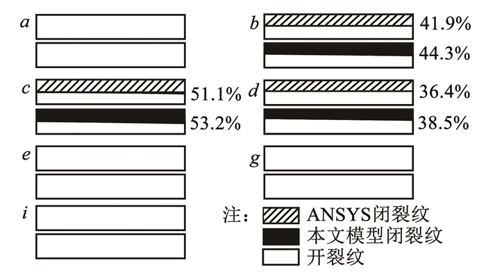
式中:fo、fh分别为开裂纹叶片第1阶固有频率和健康叶片第1阶固有频率。取裂纹位置比λ=Lc/L=0.2;裂纹深度比ζ=a/hsc=0.25;气动力幅值A=0.1 MPa;斜裂纹角度θ=10°,计算100个周期且其中每个周期计算128个载荷步。在一个周期内取9个点进行静力求解,如图 8、9所示。

|
图 8 一个周期内的采样点 Fig. 8 Sampling points in one period |

|
图 9 呼吸状态对比 Fig. 9 Comparison of breathing states |
图 9中百分数表示闭裂纹区域占整个裂纹面的面积比,从图中可以看出,当气动力为正时,随着气动力幅值的增大,裂纹面的接触面积也相应增大;气动力幅值减小,接触面积也相应减小。当气动力幅值为负时表现为开裂纹,两个裂纹面无接触,因此图 9中下半周期只给出了3个采样点的呼吸状态。本文模型与ANSYS接触模型均表现出了同样的规律,因此本文模型可以判断裂纹面的呼吸状态及接触区域变化情况。
在非线性系统中,当外激励频率的倍频接近系统固有频率时产生的共振称为超谐共振;相反地,当外激励频率的分频接近系统固有频率时产生的共振称为亚谐共振。由于超谐共振的产生所需要的激振频率相对较小,而第1阶共振时产生的振动幅值较大,在实际工程应用中,超谐共振和第1阶共振往往会引起较大的危险。因此本文将激励频率fe分别取0.5倍和1.0倍的叶片第1阶呼吸频率来验证旋转扭形斜裂纹叶片的响应特性。
取斜裂纹角度为10°,裂纹位置比λ=0.2;裂纹深度比ζ=0.25;气动力幅值A=0.1 MPa;激励频率fe=0.5fbreathing与fe=1.0fbreathing;转速n=60fe/ke,ke为静子叶片数,本文取10。裂纹叶片叶尖点弯曲方向的振动响应结果如图 10所示。为了凸显幅值较低的频率成分,本文给出对数频谱图,由图 10可知,在超谐共振与第1阶共振状态下均出现了倍频成分,说明裂纹的出现引起了非线性现象。在FFT谱图中,0fe为常值分量,表示叶片裂纹引起的平衡位置的偏移量。从图 10中还可以得出:超谐共振状态下的1.0fe幅值与2.0fe幅值大小更加接近,这是因为超谐共振状态下2.0fe对应的频率接近裂纹叶片的第1阶固有频率。

|
图 10 θ=10°时叶尖点Yr向的振动响应 Fig. 10 Vibration response of blade tip in Yr-direction at θ=10° |
将本文模型与ANSYS模型得到的超谐共振与第1阶共振状态下的振动响应进行对比,计算时间与倍数关系见表 2。其中计算机硬件条件为:Intel(R), i7-9700, CPU 3.00 GHz;本文模型自由度为600,采用MATLAB R2020b进行计算,而ANSYS有限元模型的自由度则达到了31 239,采用ANSYS R19.2计算。根据表 2中倍数关系可知,本文模型的计算效率远远大于ANSYS软件计算效率,其中,tA表示ANSYS有限元模型计算时间,tp表示本文模型计算时间。
| 表 2 ANSYS模型与本文模型计算效率对比 Tab. 2 Comparison of calculation efficiency between ANSYS model and proposed model |
本文取裂纹位置比λ=0.2、裂纹深度比ζ=0.50,研究斜裂纹角度变化对裂纹叶片第1阶固有频率的影响,不同斜裂纹角度的固有频率对比如图 11所示。从图 11中可以看出,当裂纹角度从0°变化到80°时,根据下式可知,固有频率增加了约3%,即随着裂纹角度的增加,裂纹接触面积发生改变,间接改变实际裂纹位置,使得等效裂纹位置离叶根越远,系统结构刚度越大,固有频率增加。
| $ \Delta f=\frac{f_0-f_{80}}{f_0} \times 100 \% $ | (18) |

|
图 11 不同裂纹角度下的固有频率 Fig. 11 Natural frequencies under different slant crack angles |
式中f0、f80为裂纹角度为0°和80°时的固有频率。
3.2 响应特性本文研究了在定转速下不同的裂纹角度对旋转裂纹叶片响应特性的影响。取转速n=1 000 r/min、λ=0.2、ζ=0.50,分别研究裂纹叶片在第1阶共振状态和超谐共振状态下,不同裂纹角度对旋转裂纹叶片非线性特性的影响,其三维对数谱图如图 12所示,倍频成分始终存在于频谱图中,说明随着裂纹角度的增加,由裂纹呼吸效应诱发的非线性振动也始终存在。

|
图 12 不同裂纹角度下的三维谱图 Fig. 12 Spectrum cascades under different slant crack angles |
由于对数图无法直观的体现频率成分对应幅值的变化规律,本文将超谐共振和第1阶共振状态下的0fe、1.0fe、2.0fe幅值变化对比于图 13中。由图 13可知,随着裂纹角度的增加,各个频率成分所对应的幅值均减小,这是因为裂纹角度越大,系统刚度越大,位移响应的幅值则越小。同时,在第1阶共振状态下,斜裂纹角度从0°变化到80°时,采用式(18)相同的计算方法可知,其1.0fe幅值降低了约40%。

|
图 13 不同斜裂纹角度下倍频幅值变化 Fig. 13 Multiple frequency amplitude changes under different slant crack angles |
1) 考虑裂纹角度对叶片动力学建模的影响,本文推导了新的含裂纹角度的应力强度因子表达式与柔度矩阵;考虑叶片呼吸效应,建立了含斜裂纹旋转扭形叶片的动力学模型,该模型能精确模拟斜裂纹叶片振动。
2) 随着裂纹角度的增加(即裂纹的等效位置离叶根越远),旋转裂纹叶片的固有频率越大,同时其倍频处所对应的幅值越来越小;并且在第1阶共振状态时1.0fe幅值变化最大,降低了约40%。
3) 通过与ANSYS有限元模型对比验证了本文模型的有效性,本文模型极大地提高了计算速度,在计算动力学响应特性时约为ANSYS有限元软件的22倍。
| [1] |
RAFIEE M, NITZSCHE F, LABROSSE M. Dynamics, vibration and control of rotating composite beams and blades: A critical review[J]. Thin-Walled Structures, 2017, 119: 795. DOI:10.1016/j.tws.2017.06.018 |
| [2] |
MA Hui, YIN Fanli, GUO Yuzhu, et al. A review on dynamic characteristics of blade-casing rubbing[J]. Nonlinear Dynamics, 2016, 84(2): 437. DOI:10.1007/s11071-015-2535-x |
| [3] |
NEVES A C, SIMÕES F M F, PINTO DA COSTA A. Vibrations of cracked beams: Discrete mass and stiffness models[J]. Computers & Structures, 2016, 168: 68. DOI:10.1016/j.compstruc.2016.02.007 |
| [4] |
MA Hui, LU Yang, WU Zhiyuan, et al. A new dynamic model of rotor-blade systems[J]. Journal of Sound and Vibration, 2015, 357: 168. DOI:10.1016/j.jsv.2015.07.036 |
| [5] |
SHE Houxin, LI Chaofeng, TANG Qiansheng, et al. The investigation of the coupled vibration in a flexible-disk blades system considering the influence of shaft bending vibration[J]. Mechanical Systems and Signal Processing, 2018, 111: 545. DOI:10.1016/j.ymssp.2018.03.044 |
| [6] |
吴志渊, 闫寒, 吴林潮, 等. 旋转裂纹叶片-弹性轮盘耦合系统振动特性[J]. 航空学报, 2022, 43(9): 625442. WU Zhiyuan, YAN Han, WU Linchao, et al. Vibration characteristics of rotating cracked-blade-flexible-disk coupling system[J]. Acta Aeronautica et Astronautica Sinica, 2022, 43(9): 625442. DOI:10.7527/S1000-6893.2021.25442 |
| [7] |
BATAILLY A, MEINGAST M, LEGRAND M. Unilateral contact induced blade/casing vibratory interactions in impellers: Analysis for rigid casings[J]. Journal of Sound and Vibration, 2015, 337: 244. DOI:10.1016/j.jsv.2014.10.010 |
| [8] |
YUAN Jie, SCARPA F, TITURUS B, et al. Novel frame model for mistuning analysis of bladed disk systems[J]. Journal of Vibration and Acoustics, 2017, 139(3): 031016. DOI:10.1115/1.4036110 |
| [9] |
刘文光, 陈国平. 含裂纹悬臂梁的振动与疲劳耦合分析[J]. 振动与冲击, 2011, 30(5): 140. LIU Wenguang, CHEN Guoping. Coupling analysis for vibration and fatigue of a cracked cantilever beam[J]. Journal of Vibration and Shock, 2011, 30(5): 140. DOI:10.13465/j.cnki.jvs.2011.05.006 |
| [10] |
WIMARSHANA B, WU Nan, WU C. Identification of breathing cracks in a beam structure with entropy[C]//SPIE Proceedings, Nondestructive Characterization and Monitoring of Advanced Materials, Aerospace, and Civil Infrastructure 2016. Las Vegas, Nevada, USA: SPIE, 2016: 980425. DOI: 10.1117/12.2219250
|
| [11] |
HEYDARI M, EBRAHIMI A, BEHZAD M. Forced vibration analysis of a Timoshenko cracked beam using a continuous model for the crack[J]. Engineering Science and Technology, an International Journal, 2014, 17(4): 194. DOI:10.1016/j.jestch.2014.05.003 |
| [12] |
ZENG Jin, CHEN Kangkang, MA Hui, et al. Vibration response analysis of a cracked rotating compressor blade during run-up process[J]. Mechanical Systems and Signal Processing, 2019, 118: 568. DOI:10.1016/j.ymssp.2018.09.008 |
| [13] |
XIE Jingsong, ZI Yanyang, ZHANG Mingquan, et al. A novel vibration modeling method for a rotating blade with breathing cracks[J]. Science China Technological Sciences, 2019, 62(2): 333. DOI:10.1007/s11431-018-9286-5 |
| [14] |
LONG Hui, LIU Yilun, LIU Kefu. Nonlinear vibration analysis of a beam with a breathing crack[J]. Applied Sciences, 2019, 9(18): 3874. DOI:10.3390/app9183874 |
| [15] |
ZHANG Xiaodong, XIONG Yiwei, HUANG Xin, et al. Dynamic modeling of rotary blade crack with regard to three-dimensional tip clearance[J]. Journal of Sound and Vibration, 2023, 544: 117414. DOI:10.1016/j.jsv.2022.117414 |
| [16] |
DARPE A K. Coupled vibrations of a rotor with slant crack[J]. Journal of Sound and Vibration, 2007, 305(1/2): 172. DOI:10.1016/j.jsv.2007.03.079 |
| [17] |
焦卫东, 蒋永华, 施继忠, 等. 空间任意斜裂纹引起的转子刚度变化机理研究[J]. 振动工程学报, 2018, 31(3): 490. JIAO Weidong, JIANG Yonghua, SHI Jizhong, et al. Study on rotor stiffness variation mechanism caused by an arbitrary spatial slant crack[J]. Journal of Vibration Engineering, 2018, 31(3): 490. DOI:10.16385/j.cnki.issn.1004-4523.2018.03.015 |
| [18] |
MA Hui, ZENG Jin, LANG Ziqiang, et al. Analysis of the dynamic characteristics of a slant-cracked cantilever beam[J]. Mechanical Systems and Signal Processing, 2016, 75: 261. DOI:10.1016/j.ymssp.2015.12.009 |
| [19] |
LIU Chao, JIANG Dongxiang. Dynamics of slant cracked rotor for a steam turbine generator system[J]. Journal of Engineering for Gas Turbines and Power, 2017, 139(6): 062502. DOI:10.1115/1.4035323 |
| [20] |
MA Yijiang, WU Jie, QIAN Denghui, et al. Modal analysis of a beam with bilateral breathing oblique cracks[J]. Proceedings of the Institution of Mechanical Engineers, Part C: Journal of Mechanical Engineering Science, 2022, 236(16): 8905. DOI:10.1177/09544062221091751 |
| [21] |
POURSAEIDI E, BAKHTIARI H. Fatigue crack growth simulation in a first stage of compressor blade[J]. Engineering Failure Analysis, 2014, 45: 314. DOI:10.1016/j.engfailanal.2014.06.018 |
| [22] |
LIU Jun, SHAO Yiming, ZHU Weidong. Free vibration analysis of a cantilever beam with a slant edge crack[J]. Proceedings of the Institution of Mechanical Engineers, Part C: Journal of Mechanical Engineering Science, 2017, 231(5): 823. DOI:10.1177/0954406216631006 |
| [23] |
ZENG Jin, MA Hui, YU Kun, et al. Coupled flapwise-chordwise-axial-torsional dynamic responses of rotating pre-twisted and inclined cantilever beams subject to the base excitation[J]. Applied Mathematics and Mechanics, 2019, 40(8): 1053. DOI:10.1007/s10483-019-2506-6 |
| [24] |
DARPE A K, GUPTA K, CHAWLA A. Coupled bending, longitudinal and torsional vibrations of a cracked rotor[J]. Journal of Sound and Vibration, 2004, 269(1/2): 33. DOI:10.1016/S0022-460X(03)00003-8 |
| [25] |
LEI Xuanyang, ZHANG Guicai, CHEN Jin, et al. Simulation on the motion of crankshaft with a slant crack in crankpin[J]. Mechanical Systems and Signal Processing, 2007, 21(1): 502. DOI:10.1016/j.ymssp.2005.08.007 |
| [26] |
ZHAO Chenguang, ZENG Jin, MA Hui, et al. Dynamic analysis of cracked rotating blade using cracked beam element[J]. Results in Physics, 2020, 19: 103360. DOI:10.1016/j.rinp.2020.103360 |
| [27] |
ANDREAUS U, CASINI P, VESTRONI F. Non-linear dynamics of a cracked cantilever beam under harmonic excitation[J]. International Journal of Non-linear Mechanics, 2007, 42(3): 566. DOI:10.1016/j.ijnonlinmec.2006.08.007 |
 2023, Vol. 55


