The physical process of underwater ignition is very complex when the rocket engine is fired. During the launched process of underwater vehicle with power-launched, the phenomenon of heat transfer, mass transfer and phase transition will occur between the aqueous medium and the high temperature gas. Meanwhile, the exhausted gas is injected into water and the combustion gas bubble is formed at the tail of the nozzle[1, 2, 3, 4]. Due to the inertial resistance of the water, the internal pressure of the gas bubble will increase sharply at the instant of the ignition[5-11], which leads the thrust of rocket engine to grow and reach a peak, and then decrease quickly. There are several factors that will have an impact on the hydrodynamic characteristics and the underwater trajectory of the vehicle, such as the formation, necking, fracture and shedding of the combustion gas bubble and the increasing thrust in the process of underwater ignition.
There are some literatures about the study on the underwater launched vehicle. In aspect of fluid flows for underwater ignition, Wang et al.[11] investigated the distribution of temperature and pressure of tail flow field by introducing influence of heat transfer and phase transition in different mediums when the rocket engine works under the water. Zhu et al.[12] combined the two-dimension model with volume of fluid model to build a simulation model on the flow field of high-speed jet at the incipient of underwater ignition; Nguyen et al.[13] analyzed the fluid flows of gas jets impinging onto liquid pools using the commercial CFD code, FLUENT; it proposed an isobaric bubble model for the underwater ignition in Ref. [14], where Euler-Lagrangian method was adopted to simulate the evolution of the bubble; In aspect of the trajectory for underwater launched vehicle, Tang et al.[15, 16] researched the trajectory of vertical underwater launched missile based on MATLAB; the unsteady simulation coupled with the hydrodynamics and ballistic trajectory based on 3D in 6 degrees of freedom was carried out based on the CFD theory and dynamic mesh technology in Ref. [17].
However, it is time-consuming to do the numerical computation for the above literatures which refer to complicated numerical methods of the underwater ignition. In regard to the studies on the trajectory for the underwater launched vehicle, the engine thrust is usually assumed as a constant in some articles. In addition, the thrust fluctuation during ignition is also ignored. In this paper, based on Rayleigh-Plesset equation, a simplified model for the motion of combustion gas bubble is proposed, which has the advantages of simple structure and a little computation. And then, by means of combining the bubble dynamic equation with the motion equation in the longitudinal plane, a mathematical model for the trajectory of underwater launched vehicle is presented. Compared the experiment results with the simulation results, it shows that the proposed model is reasonable and validity which can describe the process of the underwater ignition and the vehicle motion.
2 Mathematical Model 2.1 Model of Combustion Gas BubbleFirstly it is assumed that the geometry of the combustion gas bubble is spherically symmetric, and the motion of a single spherical bubble in free water area is investigated. Compared with the depth of bubble, the dimension of bubble is so small and the effect of gravity is weak. Therefore, the flow caused by bubble collapse is considered as the spherically symmetric motion, and the equation of continuity for an ideal incompressible fluid can be written as
| ${\rm{4}}\pi {{\rm{r}}^2}{V_r}\left( {r, t} \right) = 4\pi {R^2}R$ | (1) |
where$R = dR/dt$; R is the radius of the bubble; r is the distance between the bubble center; Vr is the induced velocity caused by the bubble motion.
The fluid viscosity is ignored, and the flow outside the bubble is considered as a potential flow of the incompressible inviscid fluid. There exists the velocity potential function as follows:
| $\varphi = \int_r^{20} {{V_r}dr = -{R^2}R/{\rm{r}}} $ | (2) |
Without considering the gravity condition, at the boundary of bubble, r=R, let the pressure of bubble is pb and substitute Eqs.(1) and (2) into the unsteady Bernoulli equation, we can have the Rayleigh-Plesset[18, 19] equation as
| $RR = {3 \over 2}{R^2} = {{{p_b}-{p_\infty }} \over p}$ | (3) |
where ρ is the water density; pb is the bubble pressure; ${{p_\infty }}$ is the water pressure at infinity.
p0 stands for the pressure at the inlet of the nozzle (Laval nozzle). Under the assumption that the flow in the nozzle is a quasi one-dimensional flow, the exit velocity VE and the mass flow Q are calculated according to different values of p0/pb. At first, it is necessary to investigate the three critical flow states[20] in the following sections:
StateⅠ: for the case of isentropic subsonic flow, Mach number at the throat of nozzle is 1. At the same time, the pressure at the exit of the nozzle pE is equal to pb, and then we can obtain the area-Mach number relation and the express of ${\left( {{{{p_b}} \over {{p_0}}}} \right)_{\rm I}}$ as
| ${{{A_E}} \over {{A^*}}} = {\left( {{2 \over {1 + \gamma }}} \right)^{{{\gamma + 1} \over {2\left( {\gamma -1} \right)}}}}{1 \over {{M_{EI}}}}{\left( {1 + {{\gamma -1} \over 2}M_{EI}^2} \right)^{{{\gamma + 1} \over {2\left( {\gamma -1} \right)}}}}$ | (4) |
| ${\left( {{{{p_b}} \over {{p_{_0}}}}} \right)_{\rm I}} = {\left( {1 + {{\gamma -1} \over 2}M_{EI}^2} \right)^{-{\gamma \over {\gamma -1}}}}$ | (5) |
where AE is the exit area; A* is the throat area; γ is the isentropic exponent; MEΙ is the exit Mach number under the state Ⅰ; $\left( {{{{p_b}} \over {{p_{_0}}}}} \right)$ is the pressure ratio under the state Ⅰ.
StateⅡ: the flows in the upstream and downstream of the throat are subsonic and supersonic respectively. In addition, a normal shock wave is right at the exit of the nozzle. At the same time pE and pb are the pressures ahead and behind of the normal shock wave respectively. Through Eqs.(4) and (5), we can obtain (pE/p0)Ⅱ and the Mach number MEⅡ. Based on the normal shock wave relations, pEⅡ can be expressed as
| ${{{p_b}} \over {{p_{E{\rm I}{\rm I}}}}} = {{2\gamma } \over {\gamma + 1}}M_{E{\rm I}{\rm I}}^2-{{\gamma -1} \over {\lambda + 1}}$ | (6) |
Then, (pb/p0)Ⅱ is given by
| ${\left( {{p_b}/{p_0}} \right)_{{\rm I}{\rm I}}} = {{{p_b}} \over {{p_{E{\rm I}{\rm I}}}}}{{{p_{E{\rm I}{\rm I}}}} \over {{p_0}}}$ | (7) |
StateⅢ: the oblique shock wave at the exit is transformed into the Mach wave. Under this condition, pE=pb, MEⅢ=MEⅡ>1, the expression for ${\left( {{{{p_b}} \over {{p_0}}}} \right)_{{\rm I}{\rm I}{\rm I}}}$ as
| ${\left( {{{{p_b}} \over {{p_0}}}} \right)_{{\rm I}{\rm I}{\rm I}}} = {\left( {1 + {{\gamma -1} \over 2}M_{_{E{\rm I}{\rm I}{\rm I}}}^2} \right)^{-{\gamma \over {\gamma -1}}}}$ | (8) |
According to theabove analyses, the exit pressure pE, the exit velocity VE and the mass flow Q with different values of p0/pb can be written as follows:
| ${P_E} = \left\{ {\matrix{ {{p_b}{{{p_b}} \over {{p_0}}} > {{\left( {{{{p_b}} \over {{p_0}}}} \right)}_{{\rm I}{\rm I}}}} \cr {{{\left( {1 + {{\gamma -1} \over 2}M_{_{E{\rm I}{\rm I}}}^2} \right)}^{-{\gamma \over {\gamma -1}}}}{p_0}{{{p_b}} \over {{p_0}}} = {{\left( {{{{p_b}} \over {{p_0}}}} \right)}_{{\rm I}{\rm I}}}} \cr {{{\left( {{{{p_b}} \over {{p_0}}}} \right)}_{{\rm I}{\rm I}{\rm I}}}{p_0}{{{p_b}} \over {{p_0}}} < {{\left( {{{{p_b}} \over {{p_0}}}} \right)}_{{\rm I}{\rm I}}}} \cr } } \right.$ | (9) |
| $Q = {\left\{ {\matrix{ {\sqrt {{\gamma \over {{R_g}{T_0}}}} {P_E}{M_E}\left( {1 + {{\gamma -1} \over 2}M_E^2} \right)} \cr {\sqrt {{\gamma \over {{R_g}{T_0}}}} {p_0}{{\left( {{{\gamma + 1} \over 2}} \right)}^{-{{\gamma + 1} \over {2\left( {\gamma -1} \right)}}}}{A^*}{{{p_b}} \over {{p_0}}} \le {{\left( {{{{p_b}} \over {{p_0}}}} \right)}_{\rm I}}} \cr } } \right.^{{1 \over 2}}}{A_E}{{{P_b}} \over {{P_0}}} > {\left( {{{{p_b}} \over {{p_0}}}} \right)_{\rm I}}$ | (10) |
| ${V_E} = \sqrt {{{2\gamma } \over {\gamma -1}}{R_g}{T_0}\left[ {1-{{\left( {{{{P_E}} \over {{P_0}}}} \right)}^{{{\gamma -1} \over \gamma }}}} \right]} $ | (11) |
where Rg is the gas constant; T0 is the combustor temperature
The combustion gasejected from the nozzle is hindered by the inertial resistance of water, which can lead to sharp decrease of the gas diffusion velocity. Ignoring the kinetic energy of gas motion inside the bubble, and assuming that the ejected gas and the gas in the bubble are mixed isentropically, according to energy conservation, the bubble pressure satisfies
| ${d \over {dt}}\left( {{\rho _b}{V_b}{e_b}} \right) = -4\pi {R^2}{p_b}R + Q{e_0}$ | (12) |
where ρb is the gas density, and ${V_b} = -{4 \over 3}\pi {R^3}$ is the volume of bubble;${e_b} = {1 \over {\gamma -1}}{{{p_b}} \over {{\rho _b}}}$ is the internal energy of bubble gas; ${e_0} = {1 \over {\gamma -1}}{R_g}{T_0}$is the internal energy of gas inside the nozzle. Meanwhile, the mass flow Q inside the nozzle can be represented by Eq.(13).
| $Q = {d \over {dt}}\left( {{\rho _b}{V_b}} \right)$ | (13) |
Substituting Eq.(13) into Eq.(12), the relationship between pb and R is
| ${{d{p_b}} \over {dt}} = -\gamma {3 \over R}{p_b}{{dR} \over {dt}} + {{Q{R_g}{T_0}} \over {4/3\pi {R^3}}}$ | (14) |
The flow state of the nozzle and the motion of the combustion gas bubble can be solved by combining Eqs.(3), (9), (10) and (14).
2.2 Mathematical Model for Longitudinal MotionBased on the momentum theorem, ignoring the second-order terms of parameters, we can obtain the simplified equations of the motion for the longitudinal plane as follows[21]:
| $\left\{ \matrix{ \matrix{ {\left( {m + {\lambda _{11}}} \right)\dot u = T-\Delta G + {1 \over 2}\rho {V_r}^2S{C_X}\left( 0 \right)} \cr {\dot Y = {V_r} = u} \cr {{C_X}\left( 0 \right) = {C_f} + {C_r} = {{0.075} \over {{{\left( {\lg {\mathop{\rm Re}\nolimits} -2} \right)}^2}}}{{{\Omega _B}} \over S} + 1.16 \times {{10}^{-3}}} \cr {} \cr } \hfill \cr {\lambda _{11}} = {\mu _{x\rho }}{\nabla _B} \hfill \cr} \right.$ | (15) |
where m is the vehicle mass; λ11 is the added mass for the x-axis; u is the axial velocity; T is the thrust; ΔG is the negative buoyancy; VT is the vehicle velocity;S is the cross-sectional area of the vehicle; Ye is the value of the buoyant center with respect to the ground coordinate system; CX(0) is the zero-lift drag coefficient; Cf is the frictional drag coefficient; Cr is the residual drag coefficient; Re is the Reynolds number; ΩB is the wetted surface area of the vehicle; μx=0.04 is the correction coefficient; ▽B is the volume of the vehicle.
When a vehicle move sunderwater, there are four main forces such as the buoyancy, the hydrodynamic forces, the gravity and the thrust. The computational formulas for the hydrodynamic coefficients refer to Ref.[21]. And the hydrodynamic force acting on the vehicle can be written as follows:
| $T = Q{V_E} + \left( {{p_E}-{p_\infty }} \right){A_E} + \left( {{p_b}-{p_\infty }} \right)\left( {{A_s}-{A_E}} \right)$ | (16) |
where As is the tail area of the vehicle, the sum of the first term and second term in Eq.(16) is the pneumatic thrust, and the third term in Eq.(16) is the hydrodynamic thrust. The ambient pressure of the combustion gas bubble is obtained by the hydrostatic pressure at the vehicle tail:
| ${P_\infty } = {P_\alpha } + \rho gh-{G_r} \times {1 \over 2}\rho {V_r}^2$ | (17) |
where pa is the atmospheric pressure;CT is the correction factor for the tail pressure.
The thrust equation and the motion equation for the longitudinal plane can be associated through Eqs.(16) and (17). The fourth-order Runge-Kutta method is employed to solve the above equations.
3 Simulation and Analysis 3.1 Hydrodynamic Analysis of Underwater Ignition at Different DepthsTo investigate the influence of the water depth h on the tail bubble pressure and the engine thrust, several numerical computations are carried out for the cases of different initial water depths, for instance the depths are chosen as 10 m, 30 m, 50 m and 70 m respectively. And the other parameters are chosen as follows: the stagnation temperature T0=3 300 K, the stagnation pressure p0=8 MPa, the throat area A*=1.25×10⁻³m2, the exit area AE=0.012 2 m2, the isentropic exponent γ=1.4, the gas constant Rg=287.6 m2/s2·K.
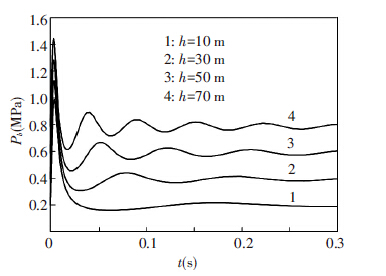
Simulation results are shown in Fig.1~Fig.6. From Fig.1, the bubble pressure as a function of time at different depths, it can be seen that the gas flow is restricted due to the high inertia of the water around the nozzle exit. As a result, this restriction leads to a shape rise of the bubble pressure, as well as a higher pressure peak. With the growth of the bubble, the bubble pressure decreases rapidly, and then it tends to oscillate around the hydrostatic pressure; through the comparison of the bubble pressure at different depths, it can be seen that the larger the water depth is, the more obvious the obstructive effect becomes, and the slower the expansion of the bubble is. Hence, the peak of the bubble pressure increases to a certain extent, and then the bubble pressure presents obvious oscillatory behavior.
|
Figure 1 Time history of bubble pressure at different depths |

|
Figure 2 Time history of thrust at different depths |
|
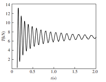
Figure 3 Time history of thrust without peak |
|
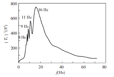
Figure 4 Power spectrum of the thrust without peak |
|
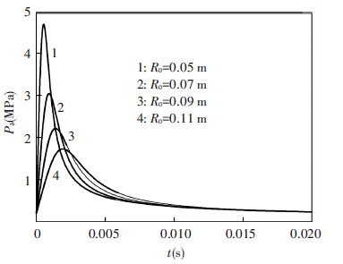
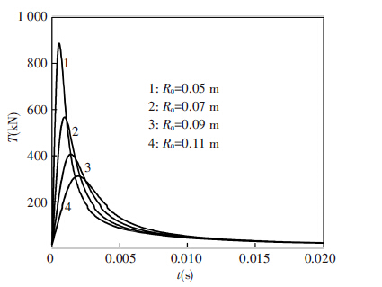
Figure 5 Time history of bubble pressure at different initial radius |
|
Figure 6 Time history of thrust at different initial radius |
As shown in Fig.2, the variation tendency of the engine thrust is similar to the bubble pressure. With the increase of the depth, the aerodynamic thrust term in Eq.(16) remains the same. However, the hydrostatic pressure and the bubble pressure of the hydrodynamic thrust term both partly increases. Considering the two above factors, the thrust peak will slightly decline. Therefore, the adjustment of the depth cannot change the thrust peak effectively. On the other side, after the thrust is stable, the hydrostatic pressure in the thrust formula will dominate because of the decline of the bubble pressure. Hence, with the increase of the depth, the stable thrust becomes smaller, and the fluctuation around the stable thrust is more obvious.
In order to investigate the effects of the thrust fluctuation on the vehicle, the thrust peak is eliminated, and the power spectrum is obtained by the way of the Fourier transform. As shown in Fig.3 and Fig.4, it can be seen that the amplitude of the thrust decreases gradually after the thrust falls from the peak, and the thrust exhibits low-frequency oscillations whose concentrated frequencies are 8 Hz, 9 Hz, 11 Hz and 16 Hz.
Fig.5 and Fig.6show the variations of bubble pressure and thrust with time when the initial radius of gas bubble changes. It can be seen that the change trend of the thrust is similar to the bubble pressure, and the thrust peak has decreased sharply with the increase of initial bubble radius. The amplitude of thrust peak falls to about one third of its original value when the initial bubble radius increases from 0.05 m to 0.11 m. At the same time, the shape of thrust peak becomes gentler and the peak arrival time has been postponed. As a result, we can reduce the thrust peak effectively by means of increasing the initial bubble radius.
3.2 Trajectory SimulationThe underwater trajectory for a vehicle launched vertically upward is simulated based on the established mathematical model, and is compared with the results of the model experiment. The experimental parameters are shown as follows: the slenderness ratio λ is 7, andthe distance between the buoyant centre and the vehicle head is 0.53L, and the mass centre is 0.028 8L behind the buoyant centre, and the water depth is 13.8 L, where L is the vehicle length. The expansion ratio of the nozzle AE/A* is 9.1, and the stagnation pressure is 7 MPa, and the stagnation temperature is 2 600 K, and the working time of the engine is 1.2 s.
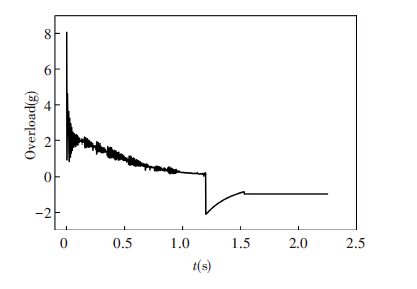
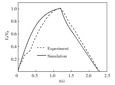
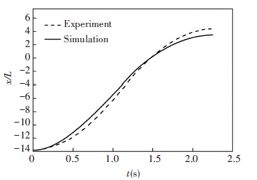
The simulation results are shown in Fig.7~Fig.9, where VM is the maximum dimensionless speed and x is the dimensionless displacement. As shown in Fig.7, the overload peak during the ignition is about 5 times larger than the average overload. The comparisons between the simulated trajectory and the experimental results are shown in Fig.8 and Fig.9. It can be seen that the axial acceleration of the vehicle achieves the maximum value when the engine is started, and then the acceleration declines gradually due to the increasing drag. The vehicle reaches the maximum speed at t≈1.2 s when the engine is stall. At t≈1.4 s, the vehicle emerges from the water, and moves to the highest point at t≈2.25 s. Overall, the results of the trajectory simulation are in a good agreement with the experimental data, and it shows that this trajectory model can effectively reflect the characteristics of the trajectory for the underwater launched vehicle, and also has a certain value for engineering application.
|
Figure 7 Time history of overload |
|
Figure 8 Time history of dimensionless speed |
|
Figure 9 Time history of dimensionless displacement |
4 Conclusions
Based on the Rayleigh-Plesset equation and the motion equation of the underwater vehicle in the longitudinal plane, this paper proposes a mathematical model for the trajectory of the underwater launched vehicle, which has the advantages of simpler structure and less computation. The important conclusions can be drawn as follows from the simulation results:
1) The nozzle flow will be choked at the initial period of the underwater ignition, which results in a high thrust peak due to the inertia effect of water, and then the thrust will stabilize gradually with the low-frequency oscillation;
2) The higher instant overload caused by the thrust pulse may do some damages to the structure and internal instruments of the vehicle during the process of underwater ignition, while the overload have little influence on the underwater vehicle trajectory because of the shortly duration of pulse;
3) With the increase of the water depth, the thrust peak and the stable thrust both decrease slightly, and the fluctuation around the stable thrust becomes more obvious. In addition, increasing the initial radius of gas bubble can reduce the thrust peak effectively;
4) The simulation results agree with the experimental data on the whole, so this mathematical model can approximately describe the process of underwater vehicle with power-launched and can be applied for the trajectory prediction.
The above conclusions can provide some references for the relevant engineering applications.
| [1] |
Chen Huanlong, Wang Ning. Investigation of nozzle gas jet characteristic with different launch depth underwater.
Chinese Journal of Hydrodynamics,2012, 27 (6) : 659-666.
( 0) 0)
|
| [2] |
Zhu Weibing, Chen Hong, Huang Shun. Numerical study of the process of the evolution of bubble of high-speed jet underwater.
Journal of Propulsion Technology,2010, 31 (4) : 496-502.
( 0) 0)
|
| [3] |
Cao Jiayi, Lu Chuanjing. Flow behavior during uncorking process of an underwater hot-launched missile.
Journal of Solid Rocket Technology,2011, 34 (3) : 281-284.
( 0) 0)
|
| [4] |
Hao Zongrui, Wang Leqin, Wu Dazhuan. Numerical simulation of high-speed jet flow field of underwater jet propulsion craft.
Journal of Zhejiang University(Engineering Science),2010, 44 (2) : 408-412.
( 0) 0)
|
| [5] |
Wang Peng, Ning Tengfei, Meng Peng. Computing flow field in igniting autonomous underwater vehicle using three-dimensional grids.
Journal of Northwestern Polytechnical University,2012, 30 (6) : 803-807.
( 0) 0)
|
| [6] |
Tang Jianing, Wang Ningfei. Flow structures of gaseous jets injected into water for underwater propulsion.
Acta Mechanica Sinica,2011, 27 (4) : 461-472.
( 0) 0)
|
| [7] |
Cao Jiayi, Gong Zhaoxin.
The characteristics of submerged gas jets by underwater ignition. China Ocean Press. 2014 .
( 0) 0)
|
| [8] |
Xu Xiaoqing, Deng Jian, Ren Anlu, et al. The research on high-speed gas jet of rocket nozzle underwater.
Journal of Hydrodynamics(Series B),2005, 17 (2) : 204-208.
( 0) 0)
|
| [9] |
Wang Yadong, Yuan Xulong. On the effect of bubble elasticity to sub-launch process using concentric canister launcher.
Chinese Journal of Computational Mechanics,2013, 30 (2) : 313-318.
( 0) 0)
|
| [10] |
Labotz R J. Hydrodynamic consideration and limitations in submerged rocket firings.
Journal of Spacecraft and Rockets,1965, 2 (3) : 320-324.
( 0) 0)
|
| [11] |
Wang Jianru, Zhao Shichang. Computations for solid rocketmoter tail flow underwater.
Journal of Solid Rocket Technology,2007, 30 (5) : 388-391.
( 0) 0)
|
| [12] |
Zhu Weibing, Chen Hong. Computation for exhausted-gas-bubble of underwater solid rocketmotor.
Journal of Solid Rocket Technology,2009, 32 (5) : 486-490.
( 0) 0)
|
| [13] |
Nguyen A V, Evans G M. Computational fluid dynamics modelling of gas jets impinging onto liquid pools.
Applied Mathematical Modelling,2006, 30 (11) : 1472-1484.
( 0) 0)
|
| [14] |
Lu Chuanjing, Chen Fang, Fan Hong. The fluid dynamic research on the underwater ignition of missile.
Acta Aeronautica et Astronautica Sinica,1992, 13 (4) : 124-130.
( 0) 0)
|
| [15] |
Fang Ning, Song Zhaoqing. Modeling and simulation for the underwater trajectory of submarine-based vertical-launched missile.
Journal of Naval Aeronautical and Astronautical University,2010, 25 (3) : 311-314.
( 0) 0)
|
| [16] |
Xu Xinqi, Tian Bing, Li Bingshang. The model and simulation of submarine to surface missile underwater trajectory.
Journal of Projectiles, Rockets, Missiles and Guidance,2010, 30 (5) : 149-152.
( 0) 0)
|
| [17] |
Yang Xiaoguang. Simulation about 3D flow field of missile underwater motion and water-exit process.
Journal of Ballistics,2010, 22 (1) : 107-110.
( 0) 0)
|
| [18] |
Wang Xianfu.
Cavitating and Supercavitating Flows Theory and Applications. Beijing: National Defense Industry Press. 2009 : 27 -34.
( 0) 0)
|
| [19] |
Shi Honghui, Wang Boyi, Dai Zhenqing. Research on the mechanics of underwater supersonic gas jets.
Science China,2010, 53 (3) : 527-535.
( 0) 0)
|
| [20] |
Shi Aimin, Su Mingde, Liu Jiren.
Gas Dynamics. Beijing: Science Press. 1988 : 115 -126.
( 0) 0)
|
| [21] |
Li Tiansen.
Torpedo Maneuverability. Beijing: National Defense Industry Press. 1999 : 194 -294.
( 0) 0)
|
 2016, Vol. 23


