2. Northwest Institute of Mechanical & Electrical Engineering,Xianyang 712099,Shanxi,China
The combustion chamber with the pressure-swirl nozzle had the disadvantages, such as high smoke release, uncontrollable exit temperature field, poor performance of the high-viscosity fuels atomization, and so on. The air-assist nozzle was introduced into the design of aero-engine in the 1970 s. The main feature of this fuel nozzle is the slots for the high-pressure air to improve the atomization. It has the advantages of good premixing effect, low radiant heat and low smoke release[1-3].
In recent decades, researchers had launched a series of studies on the internal flow field, the spray process and the combustion performance. They made constant innovation of the nozzle structure and the working mode. Several new-type air-assist nozzles were developed. Levy et al. [4-5] designed a miniature air-assist atomizer with an axial air swirler. They found that the droplet size is reduced significantly when the air velocity increases up to about 50 m/s. However, the liquid pressure had only a weak effect on the droplet size. Aliabadi et al. [6] studied an air-assist internally mixing nozzle, and analyzed the spatial distribution of the droplets on the transient and steady state to explore the variations of the diameter and the relaxation time for the droplets along with the turbulent intensity. Oh et al. [7] conducted the experiments of the air-assist nozzle with both internal and external mixing to see the parameter variations in the spray combustion processes, and pointed out that the spray combustion is closer to the premixing combustion with the liquid reaction and the gaseous reaction exists in the layered reaction zones. Avulapati et al.[8] demonstrated an air-assisted impinging nozzle conguration in which a gas nozzle is directed on to the impinging point of two liquid nozzles is used to improve the atomization. Sivakumar et al. [9] studied the details of liquid sheet breakup and spray development from a gas-centered swirl coaxial nozzle in ambient atmosphere. To atomize the high-viscosity fuels,Padwal et al. [10] modified the air slots in the air-assist internal mixing nozzle, and obtained a satisfactory result. Fan et al. [11] provided a combination of air-assist nozzle and pressure-swirl nozzle. They studied the atomization of the high-viscosity liquid to explore the function relation between Sauter Mean Diameter (SMD) and the kinematic viscosity.
Lin et al. [12-14] deeply studied a series of double-swirl air-assist nozzles made by General Electric (GE), such as GE90,F101,T700, and so on. They concluded the influences of the structure on the spray and combustion parameters. Zhang et al. [15] researched on the performance of a direct-jet double-swirl air-assist nozzle under different pressure drops and air-fuel ratios with Malvern laser particle size analyzer. Gong et al.[16-18] measured the spray parameters of a new-type air-assist nozzle under various conditions. This nozzle mixed air and fuel inside, swirled and jetted the mixture. The results showed that the spray performance is greatly influenced by pressure drop and air-fuel ratio, but much less by the structure of the nozzle. Wu et al. [19] discussed the effects of periodic time and mass ratio on the spray parameters of a periodical air-assist nozzle, and deduced the equation of the mean diameter for the droplets under a comparatively high pressure. Lee et al. [20] studied the pulsed air-assist liquid nozzle injected into a cross-flow and found that pulsed air-assist liquid nozzle will offer rapid mixing and good liquid nozzle penetration. Zhou et al. [21] investigated the spray characteristic of a doubt-line pressure-swirl nozzle with an air swirler, and revealed the change rules of SMD and spray cone angle with fuel injection pressure and swirled air velocity.
Based on the former researchers’ works, a new-typed air-assist nozzle is proposed. Combining the nozzle features of Levy[4-5] and Gong[16-18], dual atomization ways are used to enhance the interaction of fuel and air. One is the swirl of the air-fuel mixture inside of the central nozzle. And another is the external swirled air from the annular nozzle, which leads to the secondary breakup of the droplets. The atomization of this nozzle is investigated with 3D PDA to analyze the effects of the pressure drop on the spray parameters. CFD software is utilized to simulate the external flow fields of the nozzle. A comparative analysis between experimental and simulated data is made. The results have reference value to the research on the atomization mechanism of this new-type air-assist nozzle.
2 Experiments 2.1 Spray SystemThe spray experimental system consists of an air compressor, a liquid container, a rotameter, a check valve, two pressure gauges, two pressure regulators, an air-assist nozzle and 3D PDA. The scheme of the spray system is shown in Fig. 1. The main properties of PDA are as follows: the measurement range of velocity is -300-1 000 m/s; the measurement precision of velocity is 0.1%; the measurement range of diameter is 0.5-200 μm; the measurement precision of diameter is 1%.

|
Figure 1 Scheme of the spray system |
Fig. 2 shows the structure of the air-assist nozzle. Different from the traditional nozzles, this nozzle has two air-assist atomization ways. First is the internal mix and swirl of air and fuel. The liquid fuel enters the nozzle through the liquid swirl slots, mixes with inverse swirled air. Then, the mixture is ejected from the central nozzle to form the initial droplets. Second is external swirled air. Those initial droplets are impacted by the swirled air from the annular nozzle. The secondary breakup will occur, and the droplets will break into smaller sizes. The diameter of the central nozzle is 2 mm. The width of the annular nozzle is 3 mm. The liquid channels are 60° from the center axis, while the gas channels are inverse. The manufacturing error of the nozzle is less than 0.1%.

|
Figure 2 Structure of the air-assist nozzle |
The set of thecoordinates is shown in Fig. 3. The z-axis is defined as the center axis of the nozzle. The origin O is the center of the nozzle. The plane Oxy is vertical to the z-axis. The relation between x, y, z-axis is determined by the right-hand corkscrew rule. The measurement points are determined in cylindrical coordinates. The circumferential angle α is shown in Fig. 3. r is the distance between the origin O and the projection of the measurement points on the plane xoy. z is the distance between the measurement points and the plane Oxy. The measurement points are the intersection of the beam in PDA. Five cross-sections are respectively selected based on z=25,50,65,80 and 100 mm. The positions of the measurement points on a cross-section are shown in Fig. 4. r is the distance between the measurement points and z-axis. The measurement points are located by groups with r=0,5,10,15,20 and 25 mm. The angle of each group is 30°. There are 61 points on one cross-section. A weighted average of all measuring data on one section is taken as data treatment.

|
Figure 3 System coordinates |

|
Figure 4 Distribution of measurement points on a section |
2.2 Experimental Results and Discussions
In the experiment, the liquid container was firstly opened, and then the air compressor started. The pressure of liquid and air was adjusted by the regulators. When the spray was stable, the measurement points were set though BSA Flow software of PDA. The experiment adopted two variables that were liquid pressure drop(Pl) and air pressure drop (Pg). Two different experimental conditions were treated. There were Pl=0.1 MPa,Pg=0.2 MPa and Pl=0.15 MPa,Pg=0.3 MPa respectively. A liquid mixture was used substitute for the liquid fuel whose viscosity is 1×10⁻³ Pas.
Fig. 5(a) shows the number distribution of the mean diameter(D30) for the droplets under Pl=0.1 MPa, Pg=0.2 MPa. The range of the diameter is from 80 to 200 μm. Most of the droplets are distributed in the range of 104 to 176 μm, which occupied 83.22% of the total. Fig. 5(b) shows the number distribution of the mean diameter for the droplets under Pl=0.15 MPa,Pg=0.3 MPa. The distribution of the diameter, from 104 to 176 μm with 89.59% of the total droplets, is concentrated in the range of 104 to 152 μm. It can be seen that improving the liquid and air pressure can narrow the distribution of the diameter. And the homogeneity of the distribution becomes better. Moreover, with the increase of the nozzle pressure drop, the mean diameter of the droplets decreases significantly. That is because increasing the nozzle pressure drop improves the disturbance between liquid and air inside and outside of the nozzle, and makes the large-size droplets more likely to breakup into smaller sizes.

|
Figure 5 Number distribution of mean diameter (D30) for droplets |
Fig. 6 shows the mean diameter of the droplets changing along the center axis. The result indicates that the mean diameter of the droplets fluctuates along the center axis. This is due to the working mode of the air-assist nozzle. When the initial droplets form in the front of the nozzle, their relatively high velocity promote secondary breakup under the influence of the external air. When the distance between the droplets and the nozzle increases, the velocity of the droplets decreases. The droplets collide with each other and coalesce into larger size. Therefore, the fluctuation of the diameter appears.

|
Figure 6 Mean diameter (D30) of the droplets changing along the center axis |
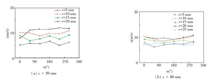
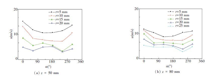
Fig. 7 shows the circumferential distribution of the axial velocity for the droplets under Pl=0.1 MPa,Pg=0.2 MPa. The axial velocity is the velocity in the z direction. The result shows that the velocity changes curve gently with a little fluctuation. That means the circumferential distribution of the axial velocity is uniform. The curves of r=5 to 25 mm rank from high to low. The further the measurement point from the center axis is, the smaller the axial velocity of the droplets is. The average velocity on the cross-section of z=50 mm in Fig. 7(a) is 9.65 m/s, higher than 9.14 m/s on the cross-section of z=80 mm in Fig. 7(b). It means that the further the cross-section from the nozzle is, the smaller the axial velocity of the droplets is. This is because when the droplets are moving along radial and axial direction, their velocity loss is mounting under aerodynamic force. Fig. 8 shows the circumferential distribution of the axial velocity for the droplets under Pl=0.15 MPa,Pg=0.30 MPa. The average velocity of the cross-section in Fig. 8(a) is 14.39 m/s, and it is 12.56 m/s in Fig. 8(b). Comparison of two working models reflects that the axial velocity of the droplets increases with the improving of the nozzle pressure drop.

|
Figure 7 Circumferential distribution of axial velocity for droplets under Pl=0.1 MPa,Pg=0.2 MPa |

|
Figure 8 Circumferential distribution of axial velocity for droplets under Pl=0.15 MPa,Pg=0.30 MPa |
3 Numerical Simulation 3.1 Physical Model
According to the characters of air-assist nozzle, some assumptions to simplify the model are made as follows:
Since the liquid have tangential velocity after it goes through the nozzle, a three-dimensional model is used to simulate the external flow fields of the nozzle.
1) Only the cold state characteristics of the spray are considered, and the influence of the temperature changes is neglected.
2) The spray is underone absolute atmosphere, and the flow of gas and liquid phase is regarded as incompressible viscous unsteady flow.
3) Because the time of spray process is short, the influence of gravity is neglected.
4) Saffman lift and surcharge force caused by shear flow is neglected.
3.2 Mathematical ModelDiscrete phase model (DPM) based on Eulerian-Lagrangian method is used for the spray process. In this model, gas phase is regarded as continuous phase, and droplets are regarded as spherical discrete phase. The track of discrete phase is achieved by solving differential equation of particle force under Lagrangian coordinates.
3.2.1 Gas phase governing equationsThe gas phase governing equations include:
1) Mass conservation equation:
| $\frac{\partial \rho }{\partial t}+\frac{\partial }{\partial {{x}_{i}}}\left( \rho {{v}_{i}} \right)=0$ | (1) |
2) Momentum conservation equation:
| $\frac{\partial \rho }{\partial t}\left( \rho {{v}_{i}} \right)+\frac{\partial }{\partial {{x}_{i}}}\left( \rho {{v}_{i}}{{v}_{j}} \right)=-\frac{\partial p}{\partial {{x}_{i}}}+\frac{\partial }{\partial {{x}_{j}}}\left[ \left( \mu +{{\mu }_{t}} \right)\frac{\partial {{v}_{i}}}{\partial {{x}_{j}}} \right]$ | (2) |
3) Turbulence model:
SSTk-ω model is selected to be the turbulence model. The equation of k is
| $\frac{\partial \left( \rho k \right)}{\partial t}+\frac{\partial \left( \rho k{{v}_{i}} \right)}{\partial {{x}_{i}}}=\frac{\partial }{\partial {{x}_{j}}}\left[ \left( \mu +\frac{{{\mu }_{t}}}{{{\sigma }_{k}}} \right)\frac{\partial k}{\partial {{x}_{j}}} \right]+{{G}_{K}}-{{Y}_{K}}$ | (3) |
The equation of ω is
| $\frac{\partial \left( \rho \omega \right)}{\partial t}+\frac{\partial \left( \rho \omega {{v}_{i}} \right)}{\partial {{x}_{i}}}=\frac{\partial }{\partial {{x}_{j}}}\left[ \left( \mu +\frac{{{\mu }_{t}}}{{{\sigma }_{\omega }}} \right)\frac{\partial \omega }{\partial {{x}_{j}}} \right]+{{G}_{\omega }}-{{Y}_{\omega }}+{{D}_{\omega }}$ | (4) |
where ρ, vi and μ are the gas density, velocity and viscosity; μt is the turbulence viscosity coefficient; Gk is the derivative coefficient of turbulence kinetic energy; Gω is the correction coefficient of the equation ω; Yk and Yω are the k and ω divergent terms caused by diffusion; Dω is the orthogonal divergent term.
3.2.2 Discrete phase governing equationsThe equation of droplet force (x-direction) in Cartesian coordinates is
| $\frac{d{{v}_{p}}}{dt}={{F}_{D}}\left( {{v}_{i}}-{{v}_{p}} \right)+{{F}_{x}}$ | (5) |
where FD(vi-vp) is the drag force per unit mass of droplet; vp is the droplet velocity; Fx is the other force in x-direction.
3.3 Geometry Model and Grid PartitionThe geometry model of the flow field is shown in Fig. 9. The calculation zone is cylinder with 200 mm diameter and 200 mm height. The air-assist nozzle is on one basal plane. The center of the nozzle coincides with the center of the circle. The boundary of the flow field is pressure boundary condition, which means spray process is under standard atmospheric pressure. A method of unstructured hexahedral elements is used for grid partition with the near-nozzle grid refined. Total number of the grids is about 15 600.

|
Figure 9 Geometry model and grid partition |
3.4 Simulation Results and Discussions
Combined with the experiment, the condition of Pl=0.1 MPa, Pg=0.2 MPa is simulated. Droplets coalescence model and TAB breakup model are chosen as the discrete phase governing model. Stochastic trajectory model is adopted to calculate the coupling between the continuous phase and the discrete phase. The drag coefficient of the droplet is obtained by dynamic drag mode. The pressure and velocity are solved simultaneously with Coupled method. The discretization of pressure is second order, and the others like momentum, energy and turbulence are second order upwind.
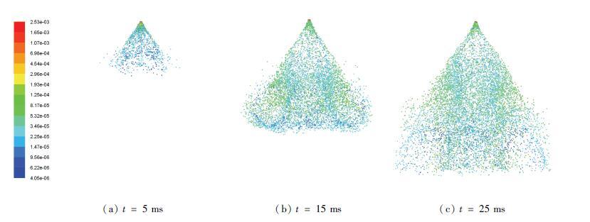
Fig. 10 shows the development sequence of the diameter distribution. It can be seen that the liquid sample is transformed into dense droplets, and these droplets move along axial and radial direction. When t=5 ms, the spray is just beginning, but the spray angle is clear to see. The comparison of the diameter distribution reflects that the droplets near the nozzle are larger than others. This is due to the influence of the airflow from the annular nozzle. The aerodynamic force facilitates the secondary breakup of the initial droplets ejected from the central nozzle, and then the smaller droplets are formed. When t=15 ms, the spray has developed over half of the calculation zone. The holistic morphology of the spray casts a cone shape with a flat head. The profile is fuzzy because of the escape of some droplets. When t=25 ms, the spray has developed beyond the boundaries. The statistical variables can be considered as steady state. The variables of t∈[25-100] ms are recorded.

|
Figure 10 Development sequence of diameter distribution for droplets |
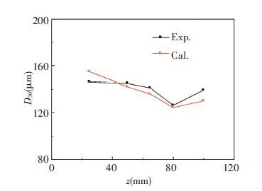
Fig. 11 shows the comparison of the diameter for the droplets between the experimental and simulated data. The result shows that the experimental and simulated data have the same trend of being fluctuating along the z-axis. The average deviation is 3.9%. That means the simulation method can be applied to study the diameter distribution of this air-assist nozzle.

|
Figure 11 Comparison between simulated and experimental data of diameter for droplets |
Fig. 12 shows the comparison of the axial velocity between the experimental and simulated data. Fig. 12(a) reflects the velocity changes along the z-axis. Fig. 12(b) is the circumferential distribution of the axial velocity on r=20 mm of the cross-section z=80 mm. Overall, the simulated result agrees well with the experimental data. The average deviations are 7.7% and 6.46% respectively. Combining the results of diameter and velocity, we deduce that the simulation errors are mainly from the differences between the real condition and the spray submodels of droplets coalescence and break up.

|
Figure 12 Comparison between simulated and experimental results of axial velocity for droplets |
4 Conclusions
Based on the former researchers’ works, a new-typed air-assist nozzle with dual atomization ways is proposed and investigated with experiment and simulation. Some initial results are concluded that:
1) With the increase of the nozzle pressure drop, the mean diameter of the droplets decreases, and the distribution uniformity of the diameter for the droplets becomes better. The mean diameter of the droplets fluctuates along the center axis.
2) The further themeasurement point from the center axis or the nozzle is, the smaller the axial velocity of the droplets is. The axial velocity of the droplets increases as the nozzle pressure drop increases.
3) The simulated result agrees well with the experimental data. The average deviation ranges from 3.9% to 7.7%. It shows that the theoretical model and the numerical simulation method given in this paper are feasible. The errors are mainly from the differences between the real condition and the spray submodels of droplets coalescence and break up.
| [1] |
Lefebvre A. Fifty years of gas turbine fuel injection.
Atomization and Sprays,2000, 10 ((3/4/5)) : 251-276.
( 0) 0)
|
| [2] |
Gan Xiaohua.
Aero Gas Turbine Engine Fuel Nozzle Technology. Beijing: National Defence Industry Press, 2006 : 41 -47.
( 0) 0)
|
| [3] |
Mellor A M.
Design of Modern Turbine Combustors. Beijing: Academic Press, 1997 : 1 -8.
( 0) 0)
|
| [4] |
Levy Y, Sherbaum V, Ovcharenko V, et al. Study of two miniature air-assist atomizers with radial and axial air swirlers. ASME 51st Turbo Expo. Barcelona: ASME, 2006. 549-556.
Levy Y, Sherbaum V, Ovcharenko V, et al. Study of two miniature air-assist atomizers with radial and axial air swirlers. ASME 51st Turbo Expo. Barcelona: ASME, 2006. 549-556. (  0) 0)
|
| [5] |
Levy Y, Sherbaum V, Ovcharenko V, et al. Experimental study of air-assist atomizers for fogging systems. ASME 51st Turbo Expo. Barcelona: ASME, 2006. 239-246.
Levy Y, Sherbaum V, Ovcharenko V, et al. Experimental study of air-assist atomizers for fogging systems. ASME 51st Turbo Expo. Barcelona: ASME, 2006. 239-246. (  0) 0)
|
| [6] |
Aliabadi A A, Lim K W J, Rogak S N, et al. Steady and transient droplet dispersion in an air-assist internally mixing cone atomizer.
Atomization and Sprays,2011, 21 (12) : 1009-1031.
( 0) 0)
|
| [7] |
Oh S H, Kim D I, Paek M S. Experiments on air-assist spray and spray flames.
Atomization and Sprays,2001, 11 (6) : 775-88.
( 0) 0)
|
| [8] |
Avulapati M M, Rayavarapu V R. Experimental studies on air-assisted impinging jet atomization.
International Journal of Multiphase Flow,2013, 57 (12) : 88-101.
( 0) 0)
|
| [9] |
Sivakumar D, Kulkarni V. Regimes of spray formation in gas-centered swirl coaxial atomizers.
Experiments in Fluids,2011, 51 (3) : 587-596.
( 0) 0)
|
| [10] |
Padwal M B, Mishra D P. Effect of air injection configuration on the atomization of gelled jet a1 fuel in an air-assist internally mixed atomizer.
Atomization and Sprays,2013, 23 (4) : 327-341.
( 0) 0)
|
| [11] |
Fan Y, Hashimoto N, Nishida H. Spray characterization of an air-assist pressure-swirl atomizer injecting high-viscosity Jatropha oils.
Fuel,2014, 121 (1) : 271-283.
( 0) 0)
|
| [12] |
Peng Yunhui, Lin Yuzhen, Xu Quanhong. Atomization, aerodynamics and combustion performance of swirl cup.
Acta Aeronautica et Astronautica Sinica,2008, 29 (1) : 1-14.
( 0) 0)
|
| [13] |
Lin Yuzhen, Lin Peihua, Xu Quanhong. Research on ignition performance of a hybrid airblast atomizer combustor with convergent-divergent sleeve.
Journal of Aerospace Power,2007, 22 (3) : 342-346.
( 0) 0)
|
| [14] |
Liu Wei, Lin Yuzhen, Liu Gaoen. Research of combustion efficiency of combustors using hybrid airblast atomizer under low pressure.
Journal of Aerospace Power,2004, 19 (5) : 650-655.
( 0) 0)
|
| [15] |
Zhang Chi, Zhang Rongwei, Xu Gguoqiang. Experimental investigation on atomization of an airblast atomizer with plain-orifice nozzle and dual-swirl cup.
Journal of Aerospace Power,2006, 21 (5) : 805-809.
( 0) 0)
|
| [16] |
Gong Jingsong, Fu Weibiao. The experimental study on the flow characteristics for a swirling gas-liquid spray atomizer.
Applied Thermal Engineering,2007, 27 (17/18) : 2886-2892.
( 0) 0)
|
| [17] |
Gong Jingsong, Fu Weibiao. A study of atomization characteristics of swirling gas-liquid spray atomizers.
Journal of Engineering for Thermal Energy and Power,2006, 21 (6) : 632-634.
( 0) 0)
|
| [18] |
Gong Jingsong, Fu Weibiao. A putting forward of a new spray atomizer and the study of its flow characterics.
Journal of Engineering Thermophyics,2005, 26 (3) : 507-510.
( 0) 0)
|
| [19] |
Wu Junze, He Xiaomin, Zhu Zhixin. Experiment on spray characteristics of periodic air-assist direct injection atomizer.
Journal of Aerospace Power,2013, 28 (2) : 307-315.
( 0) 0)
|
| [20] |
Lee I, Kang Y, Koo J. Mixing characteristics of pulsed air-assist liquid jet into an internal subsonic cross-flow.
Journal of Thermal Science,2010, 19 (2) : 136-140.
( 0) 0)
|
| [21] |
Zhou bing, Ji Honghu, Zhang Baocheng. Experiment of swirled air effect on spray characteristic of double-line pressure-swirl atomizer.
Journal of Aerospace Power,2013, 28 (9) : 1933-1941.
( 0) 0)
|
 2016, Vol. 23


