Power split gear transmission system is suitable for high speed and overloaded occasions, and is widely used in power transmission of helicopters, ships, etc[1]. But the branches of power split transmission system form a closed structure, contact each other through meshing with the input and output gear simultaneously, and inevitably produce dynamic characteristics in the operation which are different from the tandem transmission, so the dynamics study of power split gear transmission system is currently a hot issue[2-16]. In order to obtain the power split gear transmission system with small vibration and low noise, many scholars devoted to the tooth profile modification effects on the gear dynamic characteristics. In 1994, Lin and Oswald[17] considered the tooth profile modification as a time-varying gear backlash, established a single stage spur gear linear dynamic torsion model with tooth profile modification, and studied the tooth profile modification effect on spur gear dynamics characteristics. In 1999, Kahraman and Blankenship[18] studied the spur gear nonlinear dynamics characteristics with addendum modification. In 2003, Wang[19] established a single stage spur gear linear dynamic model with tooth profile modification and errors, the model considered the supporting function of bearing, and studied the tooth profile modification effect on dynamic transmission errors. In 2008, Liu and Parker[20] established the nonlinear dynamic model of a two-stage spur gear transmission, and studied the effect of tooth profile modification to nonlinear dynamic system. In the same year, Bonori and Barbieri[21] established a single stage spur gear nonlinear dynamic torsion model with tooth profile modification, and based on the model, the genetic algorithm was adopted to optimize the shape parameters. In 2011, Faggioni and Samani[22] established a single stage spur gear nonlinear dynamic model with tooth profile modification, proposed a higher efficiency of random-simplex optimization algorithm, the algorithm was used to optimize the modification parameters in order to minimize the peak of dynamic transmission error. From the foregoing, the minimized dynamic response amplitude of modification parameters can be gotten effectively through dynamic model, and the studies provide powerful theoretical guidance to the gear transmission system damping noise reduction.
A bend-torsion-shaft coupling nonlinear dynamic model of the power split transmission system is established in this dissertation, the tooth profile modification is expressed as a time-varying gear backlash function varying according to the meshing process along the meshing line direction. The effects of gear modification parameters to the system dynamics characteristics are also analyzed through numerical method, and the dissertation provides a theoretical method and reference for the selection of the optimized modification parameters.
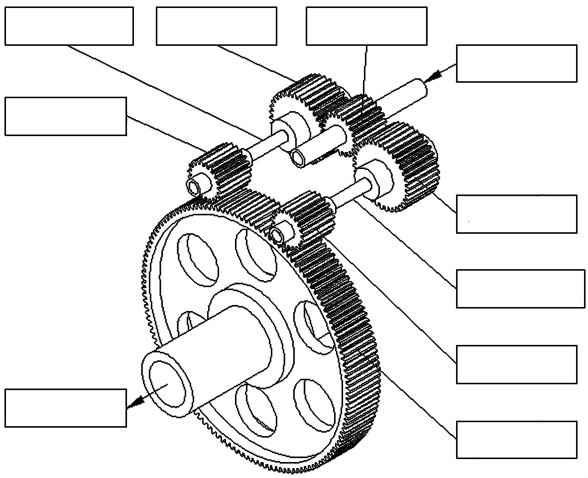
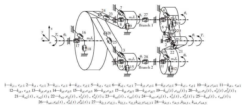
2 Dynamics Model and Equations of Power Split Transmission SystemThe power split gear transmission system is shown in Fig. 1,and the dynamic model is shown in Fig. 2.
|
Figure 1 Three-dimensional model of power split gear transmission system |
|
Figure 2 Dynamic model of power split gear transmission system |
Gear 1 meshes Gear 2 and 4 at the same time, which forms the power split. Gear 3 and 5 mesh Gear 6 at the same time, which forms the power interflow. The meaning of the parameters in Fig. 2: mi(i=1, 2, …, 6) is the mass of each node. Ii(i=1, 2, …, 6) is the rotational inertia of each node. kxi, kyi, kzi, cxi, cyi, czi(i=1, 2, …, 6) are the support stiffness and damp along the coordinate axises x, y, z. kti, j, kbi, j, ktei, j, cti, j, cbi, j, ctei, j(i=2, 4;j=3, 5) is the torsional, bending, axial stiffness and damp of the shaft between gear i, j respectively. kms(t), cms(t)(s=1, 2, 3, 4) is the time-varying mesh stiffness and damp of gear pair s. bms(s=1, 2, 3, 4) is the gear backlash along the contact line of gear pair s. ets(t)(s=1, 2, 3, 4) is the tooth profile error along the contact line of gear pair s. eirs(t)(i=1, 2, …, 6, s=1, 2, 3, 4) is the projection of the radial run out error along the contact line of Gear i of gear pair s. ets(t)(s=1, 2, 3, 4) and eirs(t)(i=1, 2, …, 6, s=1, 2, 3, 4) can be acquired by a method presented by Kubur and Kahraman[23]. The input torque acts on Gear 1 with the same direction of Gear 1, and the output torque acts on Gear 6 with the opposite direction of Gear 6.
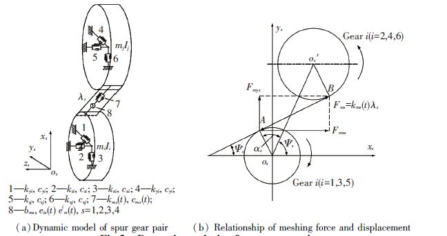
Fig. 2 shows the relationship of meshing force and displacement of spur gear pair s(s=1, 2, 3, 4). Gear i(i=1, 3, 5) is the driving gear, and Gear j(j=2, 4, 6) is the driven gear. Fig. 3(a) shows a local-coordinate xsyszs which the axis z overlaps the axle of driving gear. λs is the gear relative displacement along the meshing line of gear pair. Because of the gear backlash (bms), the meshing force (Fms) should be written as a piecewise function:
|
Figure 3 Dynamic analysis of spur gear pair |
| ${{F}_{ms}}=\left\{ \begin{align} & {{k}_{ms}}(t)({{\lambda }_{s}}-{{b}_{ms}}),{{\lambda }_{s}}>{{b}_{ms}} \\ & 0,-{{b}_{ms}}\le {{\lambda }_{s}}\le {{b}_{ms}},s=1,2,3,4 \\ & {{k}_{ms}}(t)({{\lambda }_{s}}+{{b}_{ms}}),{{\lambda }_{s}}-{{b}_{ms}} \\ \end{align} \right.$ | (1) |
The gear pair projection along the axis zs is shown in Fig. 3(b), and the driving gear rotating direction is clockwise. Fmxs and Fmys are the component forces along the axises xs, ys. αs is the gear pressure angle; ψs is the relative position angle between two gear, and Ψs is the angle between the meshing line and the axises xs. xi, yi, zi, xj, yj, zj are the displacements of gear i, j along the axises xs, ys, zs respectively, and θi, θj are the angular displacements around the axis zs. The relative displacement along the meshing line is shown as follows:
| $\eqalign{ & {\lambda _s} = ({x_i} - {x_j})\cos {\psi _s} + ({y_i} - {y_j})\sin {\psi _s} + {r_i}{\theta _i} - \cr & {r_j}{\theta _j} + e_{rs}^i(t) + e_{rs}^j(t) - {e_{ts}}(t) \cr} $ | (2) |
According to Newton′s second law, the dynamics equations of power split gear transmission system are deduced in the way of lumped parameter method[24-26] as follows:
| $\left\{ \begin{align} & {{m}_{1}}{{{\ddot{x}}}_{1}}+{{k}_{x1}}{{x}_{1}}+{{c}_{x1}}{{{\dot{x}}}_{1}}=-{{F}_{mx1}}-{{F}_{mx2}} \\ & {{m}_{1}}{{{\ddot{y}}}_{1}}+{{k}_{y1}}{{y}_{1}}+{{c}_{y1}}{{{\dot{y}}}_{1}}=-{{F}_{my1}}-{{F}_{my2}} \\ & {{m}_{1}}{{{\ddot{z}}}_{1}}+{{k}_{z1}}{{z}_{1}}+{{c}_{z1}}{{{\dot{z}}}_{1}}=0 \\ & {{I}_{1}}{{{\ddot{\theta }}}_{1}}=-{{F}_{m1}}{{r}_{1}}-{{F}_{m2}}{{r}_{1}}+{{T}_{1}} \\ & {{m}_{2}}{{{\ddot{x}}}_{2}}+{{k}_{x2}}{{x}_{2}}+{{c}_{x2}}{{{\dot{x}}}_{2}}+{{k}_{b2,3}}({{x}_{2}}-{{x}_{3}})+{{c}_{b2,3}}({{{\dot{x}}}_{2}}-{{{\dot{x}}}_{3}})={{F}_{mx1}} \\ & {{m}_{2}}{{{\ddot{y}}}_{2}}+{{k}_{y2}}{{y}_{2}}+{{c}_{y2}}{{{\dot{y}}}_{2}}+{{k}_{b2,3}}({{y}_{2}}-{{y}_{3}})+{{c}_{b2,3}}({{{\dot{y}}}_{2}}-{{{\dot{y}}}_{3}})={{F}_{my1}} \\ & {{m}_{2}}{{{\ddot{z}}}_{2}}+{{k}_{z2}}{{z}_{2}}+{{c}_{z2}}{{{\dot{z}}}_{2}}+{{k}_{te2,3}}({{z}_{2}}-{{z}_{3}})+{{c}_{te2,3}}({{{\dot{z}}}_{2}}-{{{\dot{z}}}_{3}})=0 \\ & {{I}_{2}}{{{\ddot{\theta }}}_{2}}+{{k}_{t2,3}}({{\theta }_{2}}-{{\theta }_{3}})+{{c}_{te2,3}}({{{\dot{\theta }}}_{2}}-{{{\dot{\theta }}}_{3}})={{F}_{m1}}{{r}_{2}} \\ & {{m}_{3}}{{{\ddot{x}}}_{3}}+{{k}_{x3}}{{x}_{3}}+{{c}_{x3}}{{{\dot{x}}}_{3}}+{{k}_{b2,3}}({{x}_{3}}-{{x}_{2}})+{{c}_{b2,3}}({{{\dot{x}}}_{3}}-{{{\dot{x}}}_{2}})={{F}_{mx3}} \\ & {{m}_{3}}{{{\ddot{y}}}_{3}}+{{k}_{y3}}{{y}_{3}}+{{c}_{y3}}{{{\dot{y}}}_{3}}+{{k}_{b2,3}}({{y}_{3}}-{{y}_{2}})+{{c}_{b2,3}}({{{\dot{y}}}_{3}}-{{{\dot{y}}}_{2}})={{F}_{my3}} \\ & {{m}_{3}}{{{\ddot{z}}}_{3}}+{{k}_{z3}}{{z}_{3}}+{{c}_{z3}}{{{\dot{z}}}_{3}}+{{k}_{te2,3}}({{z}_{3}}-{{z}_{2}})+{{c}_{te2,3}}({{{\dot{z}}}_{3}}-{{{\dot{z}}}_{2}})=0 \\ & {{I}_{3}}{{{\ddot{\theta }}}_{3}}+{{k}_{t2,3}}({{\theta }_{3}}-{{\theta }_{2}})+{{c}_{te2,3}}({{{\dot{\theta }}}_{3}}-{{{\dot{\theta }}}_{2}})={{F}_{m3}}{{r}_{3}} \\ & {{m}_{4}}{{{\ddot{x}}}_{4}}+{{k}_{x4}}{{x}_{4}}+{{c}_{x4}}{{{\dot{x}}}_{4}}+{{k}_{b4,5}}({{x}_{4}}-{{x}_{5}})+{{c}_{b4,5}}({{{\dot{x}}}_{4}}-{{{\dot{x}}}_{5}})={{F}_{mx2}} \\ & {{m}_{4}}{{{\ddot{y}}}_{4}}+{{k}_{y4}}{{y}_{4}}+{{c}_{y4}}{{{\dot{y}}}_{4}}+{{k}_{b4,5}}({{y}_{4}}-{{y}_{5}})+{{c}_{b4,5}}({{{\dot{y}}}_{4}}-{{{\dot{y}}}_{5}})={{F}_{my2}} \\ & {{m}_{4}}{{{\ddot{z}}}_{4}}+{{k}_{z4}}{{z}_{4}}+{{c}_{z4}}{{{\dot{z}}}_{4}}+{{k}_{te4,5}}({{z}_{4}}-{{z}_{5}})+{{c}_{te4,5}}({{{\dot{z}}}_{4}}-{{{\dot{z}}}_{5}})=0 \\ & {{I}_{4}}{{{\ddot{\theta }}}_{4}}+{{k}_{t4,5}}({{\theta }_{4}}-{{\theta }_{5}})+{{c}_{te4,5}}({{{\dot{\theta }}}_{4}}-{{{\dot{\theta }}}_{5}})={{F}_{m2}}{{r}_{4}} \\ & {{m}_{5}}{{{\ddot{x}}}_{5}}+{{k}_{x5}}{{x}_{5}}+{{c}_{x5}}{{{\dot{x}}}_{5}}+{{k}_{b4,5}}({{x}_{5}}-{{x}_{4}})+{{c}_{b4,5}}({{{\dot{x}}}_{5}}-{{{\dot{x}}}_{4}})={{F}_{mx4}} \\ & {{m}_{5}}{{{\ddot{y}}}_{5}}+{{k}_{y5}}{{y}_{5}}+{{c}_{y5}}{{{\dot{y}}}_{5}}+{{k}_{b4,5}}({{y}_{5}}-{{y}_{4}})+{{c}_{b4,5}}({{{\dot{y}}}_{5}}-{{{\dot{y}}}_{4}})={{F}_{my4}} \\ & {{m}_{5}}{{{\ddot{z}}}_{5}}+{{k}_{z5}}{{z}_{5}}+{{c}_{z5}}{{{\dot{z}}}_{5}}+{{k}_{te4,5}}({{z}_{5}}-{{z}_{4}})+{{c}_{te4,5}}({{{\dot{z}}}_{5}}-{{{\dot{z}}}_{4}})=0 \\ & {{I}_{5}}{{{\ddot{\theta }}}_{5}}+{{k}_{t4,5}}({{\theta }_{5}}-{{\theta }_{4}})+{{c}_{te4,5}}({{{\dot{\theta }}}_{5}}-{{{\dot{\theta }}}_{4}})={{F}_{m4}}{{r}_{5}} \\ & {{m}_{6}}{{{\ddot{x}}}_{6}}+{{k}_{x6}}{{x}_{6}}+{{c}_{x6}}{{{\dot{x}}}_{6}}=-{{F}_{mx3}}-{{F}_{mx4}} \\ & {{m}_{6}}{{{\ddot{y}}}_{6}}+{{k}_{y6}}{{y}_{6}}+{{c}_{y6}}{{{\dot{y}}}_{6}}=-{{F}_{my3}}-{{F}_{my4}} \\ & {{m}_{6}}{{{\ddot{z}}}_{6}}+{{k}_{z6}}{{z}_{6}}+{{c}_{z6}}{{{\dot{z}}}_{6}}=0 \\ & {{I}_{6}}{{{\ddot{\theta }}}_{6}}={{F}_{m3}}{{r}_{6}}+{{F}_{m4}}{{r}_{6}}-{{T}_{6}} \\ \end{align} \right.$ | (3) |
The nonlinear dynamics equation of power split transmission system is deduced from Eqs.(1),(2) and (3),and the matrix form is:
| $M\ddot X + {K_{com}}X + {K_t}X + C\dot X = F + {F_n} + {F_e}$ | (4) |
Where M is the mass matrix; Kcon is the constant part of stiffness matrix; Kt is the time varying part of stiffness matrix; C is the proportional damping matrix that is given as C=εK+ηM, here ε and η are proportionality constants, and the two proportionality constants could be acquired by a method presented by Clough and Penizen[27]; X is the displacement vector; F is the external excitation vector; Fn is the nonlinear excitation vector caused by the gear backlash; Fe is the excitation vector caused by the tooth profile error.
3 Gear Backlash Equation with Tooth Profile ModificationBecause the tooth profile modification is cutting a part from the original involute profile, which amounts to adding a backlash value in the process of tooth contact. However the backlash value is not constant, which is constantly changing in the meshing. And so the tooth profile modification is considered as a time-varying gear backlash along the meshing line. The gear backlash function with the tooth profile modification is:
| ${{g}_{s}}(t)=\left\{ \begin{align} & 0,0\le tt<\left( 2-{{c}_{s}} \right){{T}_{ms}}\text{or}\left( 2-{{c}_{s}}+{{\xi }_{ms}} \right){{T}_{ms}}<tt<{{T}_{ms}} \\ & -\frac{{{\rho }_{ms}}tt}{{{\xi }_{ms}}{{T}_{ms}}}+\frac{{{\rho }_{ms}}\left( 2-{{c}_{s}}+{{\xi }_{ms}} \right)}{{{\xi }_{ms}}},(2-{{c}_{s}}){{T}_{ms}}\le tt\le \left( 2-{{c}_{s}}+{{\xi }_{ms}} \right){{T}_{ms}} \\ \end{align} \right.$ | (5) |
Where tt={(t+psTms)/Tms-floor[(t+psTms)/Tms]}Tms, here t is the time value, and Tms is the meshing period, ps is the meshing phase; cs is the contact ratio; ρms is the tooth profile modification quantity(TPMQ); ξms is the proportion of modification area in the whole meshing period, which is the relative tooth profile modification length(TPML).
In consideration of the time-varying gear backlash caused by the profile modification, the nonlinear function of the gear backlash changes into the following form, and bms should replace bms in Eq.(1) during the calculation:
| ${{\bar{b}}_{ms}}=\left\{ \begin{align} & {{b}_{ms}}+{{g}_{s}}(t),{{\lambda }_{s}}>{{b}_{ms}}+{{g}_{s}}(t) \\ & {{\lambda }_{s}},{{b}_{ms}}\le {{\lambda }_{s}}\le {{b}_{ms}}+{{g}_{s}}(t) \\ & -{{b}_{ms}},{{\lambda }_{s}}-{{b}_{ms}} \\ \end{align} \right.$ | (6) |
The parameters of a power split gear transmission system are shown in Table 1.
| Table 1 Power split gear transmission system parameters |
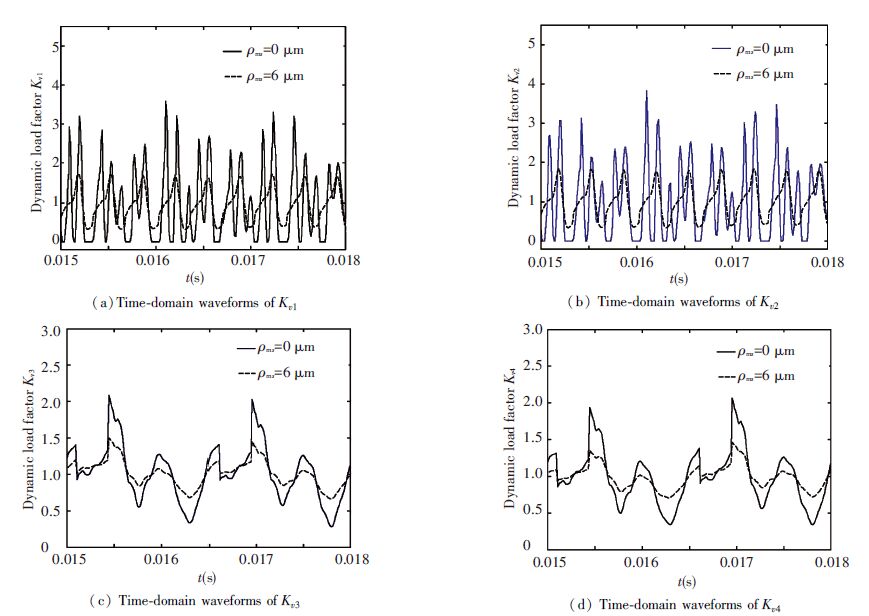
After eliminating the rigid body displacement of the equations and nondimensionalization, the simultaneous Eqs.(4), (5), (6) become second order nonlinear differential equations. In this paper the equations are solved by a numerical method, Runge-Kutta method[28], and the MATLAB ode45 function is used in the computational process. The input torque is T1=600 N·m, and the input speed is 5 500 r/min. The TPMQ of each gear pair are assumed to be equal respectively, and the relative length of the modification(TPML) is ξms=cs-1. The system dynamic load factors when ρms=0, ρms=6 μm(s=1, 2, 3, 4) are shown in Fig. 4.
|
Figure 4 Dynamic load factor with no tooth profile modification and with tooth profile modification |
Fig. 4 shows that the maximum value of the first stage transmission dynamic load factor is 3.6 in the case of ρms=0(s=1, 2, 3, 4), and a lot of zeros appear simultaneously, which shows that a phenomenon of the tooth surface complete separation arises in the first stage transmission. And the system is in a nonlinear motion state, and the maximum value of the second stage transmission dynamic load factor is 2.1. The dynamic load factors of all the gear pairs will reduce greatly in the case of ρms=6 μm(s=1, 2, 3, 4), and the maximum value of the first stage transmission dynamic load factor reduce to 1.6. Zero and negative value no longer appears, and the maximum value of the second stage transmission dynamic load factor reduced to 1.5. As described in Refs.[29-35], the tooth profile modification can reduce the gear meshing stiffness excitation and stabilize the gear meshing force. And so by means of tooth profile modification, the system vibration can be effectively alleviated and the nonlinear effects such as tooth surface separation and tooth back impact can even be inhibited.
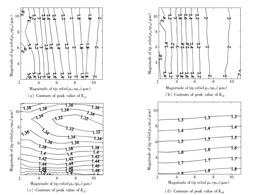
The operating conditions and parameters are mentioned above. Then in the case of different TPMQs of the first and the second stages, the maximum dynamic load factor contour of the power split transmission system is shown in Fig. 5.
|
Figure 5 Contours of peak value of dynamic load factor in different TPMQs |
As shown in Figs. 5(a) and 5(b), the peak contours of the first stage transmission dynamic load factor Kv1 and Kv2 are almost parallel to the longitudinal axis, which indicates that the effect of the first stage transmission TPMQs to Kv1 and Kv2 is greater than to the second. In the case of ρm1=ρm2<9 μm, the peaks of Kv1 and Kv2 decrease with the increase of ρm1=ρm2, and the contours are skewed slightly to the left which shows that the peaks of Kv1 and Kv2 decrease slowly with the increase of ρm3=ρm4. In the case of ρm1=ρm2>9 μm, the peaks of Kv1 and Kv2 increase with the increase of ρm1=ρm2, and the contours are skewed slightly to the right which shows that the peaks of Kv1 and Kv2 increase slowly with the increase of ρm3=ρm4. And so, if the second transmission TPMQs are ignored, the first transmission TPMQs minimized Kv1 and Kv2 is ρm1=ρm2=9 μm. As shown in Figs. 5(c) and 5(d), most of the peak contours of the second stage transmission dynamic load factor Kv3 and all of Kv4 are almost parallel to the horizontal axis, which indicates that the effect of the second stage transmission TPMQs to Kv3 and Kv4 is greater than to the first. The TPMQ that minimizes the peak of Kv3 locates in the area surrounded by the contour with value of 1.32, and the area is very narrow along the horizontal axis, which shows that the effect of the first stage transmission modification to Kv3 and Kv4 is lesser. And so, if the first transmission TPMQs are ignored, the second transmission TPMQs minimized Kv3 and Kv4 is ρm3=ρm4=9 μm. The tooth profile modification can ameliorate the gear vibration[30-33], but overlarge TPMQ will lessen the contact ratio, even enlarge the transmission error[30], which make against the stably operation of gear transmission on the contrary. ρm1=ρm2=ρm3=ρm4=9 μm are just the optimum TPMQs and in the range of the empirical value mentioned in Refs. [30-32].
In conclusion, the transmission TPMQs give a great effect on its own dynamic load factor, and give a small effect on the other transmission. So in the process of determining the TPMQs of the power split transmission system, if only for a rough estimate, the two stages of transmission can be analyzed separately, and the coupling effect between the two stages of transmission can be ignored. In fact, in the analysis of tooth profile modification of multistage gear transmission, the coupling effect of every stage is not taken into account usually, and the tooth profile modification parameters of every stage are calculated respectively[34-35].
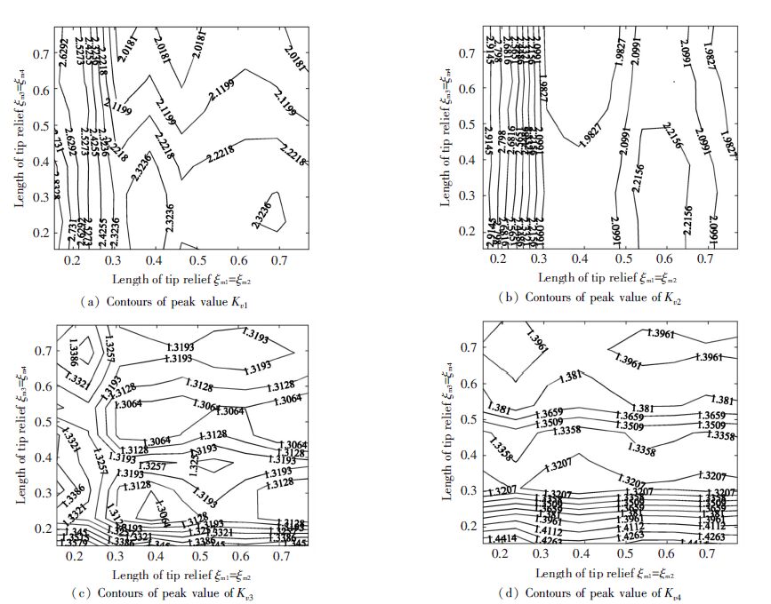
The TPMQs are assumed to be 8 μm, and the two stages of TPMLs are ξm1=ξm2<c1/2, ξm3=ξm4<c3/4 respectively. The operating conditions and other parameters are mentioned above. In the case of different TPMLs of the first and the second stage, the maximum dynamic load factor contour of the power split transmission system is shown in Fig. 6.
|
Figure 6 Contours of peak value of dynamic load factor in different TPMLs |
As shown in Figs. 6(a) and 6(b), in the case of ξm1=ξm2<0.3, the peak contours of the first stage transmission dynamic load factor Kv1 and Kv2 are almost parallel to the longitudinal axis, which indicates that the effect of the first stage TPMLs to Kv1 and Kv2 far greater than to the second, and the peaks of Kv1 and Kv2 decrease with the increase of the TPMLs ξm1=ξm2. In the case of ξm1=ξm2>0.3, both the first stage TPMLs ξm1=ξm2 and the second ξm3=ξm4 affect Kv1 and Kv2 greatly, and the relationship is relatively complicated. As shown in Figs. 6(c) and 6(d), in the case of ξm3=ξm4<0.2, the peak contours of the second stage transmission dynamic load factor Kv3 and Kv4 are almost parallel to the horizontal axis, which indicates that the effect of the second stage TPMLs to Kv3 and Kv4 far greater than the first, and the peaks of Kv3 and Kv4 decrease with the increase of the TPMLs ξm3=ξm4. In the case of ξm3=ξm4>0.2, both the first stage TPMLs ξm1=ξm2 and the second ξm
In addition, the variation of the dynamic load factor is smaller when the TPMLs vary than the TPMQs do. For example, the peaks of Kv1 and Kv2 reduce from 3.6 to 1.8, and the peaks of Kv3 and Kv4 reduce from 1.5 to 1.3 when the TPMQs vary. And the peaks of Kv1 and Kv2 reduce from 2.6 to 2.0, the peaks of Kv3 and Kv4 reduce from 1.4 to 1.35 when the TPMLs vary. That means the effect of the TPMQ to the dynamic load factor is greater than the TPML, so the TPMQ is the emphasis in the optimization of modification parameters. In accordance with the principle of the tooth profile modification, the TPMQ, the TPML and the tooth profile curve are the three elements of the tooth profile modification[29-35]. As mentioned in Ref. [30], the TPMQ could optimize the single-tooth meshing force and meshing stiffness, and mitigate the violent fluctuation of the total meshing stiffness on the premise that the proportion of the single-tooth and double-teeth meshing area are kept invariant. On the other hand, the TPML would cause the variation of the proportion of the single-tooth and double-teeth meshing area, which have a certain negative effect on the dynamic meshing forces of the gear pair. Therefore the TPMQ has more positive effect on the dynamic load factor than the TPML. As a consequence, the TPMQ should be top-priority in the modification design.
5 Conclusions1) The effect of the TPMQs of the first stage transmission to the vibration amplitude of the first stage transmission is larger than to the second stage. Similarly,the effect of the TPMQs of the second stage transmission to the vibration amplitude of the second stage is also larger than to the first stage. And the coupling effect between two stages of the power split transmission system can be ignored in the tooth profile modification design. When the TPMQs achieve optimal values,the vibration amplitude of the system would be the smallest.
2) In the case of the TPMLs of the first stage transmission ξm1=ξm2<0.3, ξm1, ξm2 affect the vibration amplitude of the first stage more greatly than the TPMLs of the second stage transmission ξm3, ξm4. In the case of ξm
3) Reasonable tooth profile modification can conspicuously reduce the vibration amplitude of the power split transmission system, and even restrain the occurrence of the nonlinear characteristics caused by the gear backlash. The TPMQs affect the vibration amplitude of the power split gear transmission system more greatly than the TPMLs, and should be top-priority in the tooth profile modification design.
| [1] |
Fan Wei, Bi Xiaoxu, Ji Guiming. Recent advances in the development of marine large and medium-sized gear transmission modes worldwide. Journal of Engineering for Thermal Energy and Power, 2003, 18(2): 208-211. ( 0) 0)
|
| [2] |
Kish J G. Sikorsky Aircraft Advanced Rotorcraft Transmission(art) Program-final Report. Cleveland: NASA Lewis Research Center, NASA CR-191079, 1993. ( 0) 0)
|
| [3] |
Krantz T L, Rashidi M, Kish J. Split torque transmission load sharing. Proceedings of the Institution of Mechanical Engineers, Part G: Journal of Aerospace Engineering, 1994, 208(2): 137-148. ( 0) 0)
|
| [4] |
( 0) 0)
|
| [5] |
Krantz T L. A method to analyze and optimize the load sharing of split-path transmissions. Cleveland: Lewis Research Center, 1996. ( 0) 0)
|
| [6] |
Krantz T L, Delgado I R. Experimental Study of Split-path Transmission Load Sharing. Cleveland: NASA Lewis Research Center, NASA TM-107212, 1996. ( 0) 0)
|
| [7] |
White G. Design study of a split-torque helicopter transmission. Proceedings of the Institution of Mechanical Engineers, Part G: Journal of Aerospace Engineering, 1998, 212(2): 117-123. ( 0) 0)
|
| [8] |
Yuan Ru, Wang Sanmin, Shen Yunwen. Dynamic optimum design of power shared out equally among the planetary gears. Journal of Aerospace Power, 2000, 15(4): 410-418. ( 0) 0)
|
| [9] |
Sun Zhimin, Shen Yunwen, Wang Sanmin, et al. Nonlinear dynamic modeling and dynamic tooth loads analysis of star gearing system. Journal of Aerospace Power, 2001, 16(4): 402-407. ( 0) 0)
|
| [10] |
Yang Zhen, Wang Sanmin, Fan Yesen. Dynamic analysis of a new split-power gear system. Mechanical Design and Manufacturing, 2007, 8: 99-101. ( 0) 0)
|
| [11] |
Yang Zhen, Wang Sanmin, Fan Yesen. Nonlinear dynamics characteristics of split-torque gear transmission system. Chinese Journal of Mechanical Engineering, 2008, 44(7): 52-57. ( 0) 0)
|
| [12] |
Singh A, Kahraman A, Ligata H. Internal gear strains and load sharing in planetary transmissions: model and experiments. Journal of mechanical design, 2008, 130(7): 072602. ( 0) 0)
|
| [13] |
Du Jiajia, Wang Sanmin, Wang Ying. Research on dynamic characteristics of power dual-path gear transmission. Machinery, 2012, 50(572): 10-13. ( 0) 0)
|
| [14] |
Dong Hao, Fang Zongde, Du Jinfu. Static load sharing characteristics analysis for power split transmission system. Journal of Harbin Institute of Technology, 2013, 9(45): 94-99. ( 0) 0)
|
| [15] |
Chang Lehao, Liu Geng, Zhou Jianxing. Research on dynamic characteristics of dual-branching gear system. Journal of Ship Mechanics, 2013, 10: 011. ( 0) 0)
|
| [16] |
Li Nan, Wang Sanmin, Du Jiajia. Natural characteristics and dynamic load coefficient of power four embranchments gear transmission. Journal of Aerospace Power, 2013, 28(2): 445-451. ( 0) 0)
|
| [17] |
Lin H H, Oswald F B, Townsend D P. Dynamic loading of spur gears with linear or parabolic tooth profile modifications. Mechanism and Machine Theory, 1994, 29(8): 1115-1129. ( 0) 0)
|
| [18] |
Kahraman A, Blankenship G. Effect of involute tip relief on dynamic response of spur gear pairs. Journal of Mechanical Design, 1999, 121(2): 313-315. ( 0) 0)
|
| [19] |
Wang Y. Optimized tooth profile based on identified gear dynamic model. Mechanism and Machine Theory, 2007, 42(8): 1058-1068. ( 0) 0)
|
| [20] |
Liu G, Parker R G. Dynamic modeling and analysis of tooth profile modification for multimesh gear vibration. Journal of Mechanical Design, 2008, 130(12). DOI:10.1115/1.2976803 ( 0) 0)
|
| [21] |
Bonori G, Barbieri M, Pellicano F. Optimum profile modifications of spur gears by means of genetic algorithms. Journal of Sound and Vibration, 2008, 313(3): 603-616. ( 0) 0)
|
| [22] |
Faggioni M, Samani F S, Bertacchi G, et al. Dynamic optimization of spur gears. Mechanism and Machine Theory, 2011, 46(4): 544-557. ( 0) 0)
|
| [23] |
Kubur M, Kahraman A, Zini D M, et al. Dynamic analysis of a multi-shaft helical gear transmission by finite elements: model and experiment. ASME Journal of Vibration and Acoustics, 2004(7): 398-406. ( 0) 0)
|
| [24] |
Yu Lie, Liu Heng. Dynamics of Rotor-Bearing System. Xi’an: Xi’an Jiaotong University Press, 2001. ( 0) 0)
|
| [25] |
Ou Weilin, Wang Sanmin, Yuan Ru. Shaft element method for the analvsis of lateral-torsional coupling vibration of a complex gear-rotor system. Jouranal of Aerospace Power, 2005, 20(3): 434-439. ( 0) 0)
|
| [26] |
Dong Jincheng, Wang Sanmin, Wang Ying. Study on the coupled bending-torsion vibration characteristics of power four-path gear transmission. Mechanical Science and Technology for Aerospace Engineering, 2014, 33(1): 1-7. ( 0) 0)
|
| [27] |
( 0) 0)
|
| [28] |
Wang Linjie. Vibration Reduction Research on Transmission System of Herringbone Gear with Elastomeric Web. Xi′an: Northwestern Polytechnical University, 2014. ( 0) 0)
|
| [29] |
Li Runfang, Wang Jianjun. Gear System Dynamics-Vibration, Impact, Noise. Beijing: Science Press, 1997. ( 0) 0)
|
| [30] |
Wang Cheng. Nonlinear Dynamic Research of Involute Spur Gear System. Beijing: Beijing Institute of Technology, 2015. ( 0) 0)
|
| [31] |
Kong Xian. Reseach on Tooth Profile Modification of Involute Helical Gear with High Speed. Nanjing: Nanjing Agricultural University, 2013. ( 0) 0)
|
| [32] |
Wang Xueyao. Research on the Theory of Profile Modification in Industrial Reducer Based on Gear Meshing Dynamics. Hefei: HeFei university of technology, 2012. ( 0) 0)
|
| [33] |
( 0) 0)
|
| [34] |
Dong Hao. Research on the Load-Sharing Characteristics of Dual Power-Split Transmission and Dynamics Analysis. Xi′an: Northwestern Polytechnical University, 2013. ( 0) 0)
|
| [35] |
Liu Huan. Research on Errors and Profile Modification of Herringbone Planetary Gear Train. Nanjing: Nanjing University of Aeronautics and Astronautics, 2014. ( 0) 0)
|
 2016, Vol. 23


