Rapid development of autonomous underwater vehicles (AUV) is witnessed along with the progress in artificial intelligence, automatic control, industrial computer, sensor and network transmission technology[1-2]. Known as an important tool for a variety of underwater tasks[3] (including dam detection[4], underwater pipeline detection[5-6], mineral resource exploration[7], relay communication[8] as well as military intelligence gathering[9], etc.), the autonomous underwater vehicle has shown a promising prospect in military and marine resource development[10-12]. Detection of seafloor resources, detection and identification of underwater objects, intelligence gathering and relay communication are the primary tasks of the autonomous underwater vehicle. Therefore, remarkable control performance and a stable work platform on the AUV are needed to perform these tasks[13-14]. It is difficult, however, to establish accurate mathematical models since the AUV is a highly nonlinear[15] and coupling system[16] in addition to the complex external environment[17] and time-varying moving conditions[18]. For this reason, focus is put on neural network[19-20] and fuzzy logic control[21-22] in studies at home and abroad. In neural network control, full considerations are made in view of the AUV's high nonlinearity and strong coupling effect among the degrees of freedom. Tracking and learning of subtle changes of the system itself and the external environment can be performed, but it is difficult to determine the parameters such as structure and weight. In addition, significantly slow learning, buffeting and even misconvergence may be caused by environment disturbance[23]. The design of fuzzy logic controller is easier and it provides higher stability, but there are demanding requirements on researchers' experiment experience in the selection of fuzzy variables and membership functions[24]. Due to the limited time and heavy workload in practice, complicated adjustment of parameters will be adverse to the application of fuzzy logic control on the AUV.
Fuzzy control rules are introduced to simple-structured PID controller and the traditional S-plane control method is provided in Ref. [25]. Based on the analysis of traditional S-plane control method, fuzzy logic reasoning and developed fuzzy nonlinear PD control method are expounded in Ref. [26]. As it is suggested by the sea trial results, low-speed control of the AUV can be performed by the traditional S-plane control method, but there is slow response and oscillation due to the lack of considerations of the coupling factors in high-speed motion. As it is suggested by the sea trial results, low-speed control of the AUV can be performed by the traditional S-plane control method, but there is slow response and oscillation due to the lack of considerations of the coupling factors in high-speed motion.
Based on a deep analysis of the mathematical model of the AUV, reference is made to the theory of sliding mode control (SMC) and a novel S-plane control method established on sliding mode control is put forward in this study. The coupling problem is solved to meet the requirement of high-speed motion control. The stability analysis of the novel controller is also carried out through Lyapunov function. Thrust allocation strategy based on constraints is proposed. Finally, the feasibility and effectiveness of the present control method is verified by comparative experiment results.
2 AUV Motion ModelingIn regard of the symmetry of AUV, its motion model can be simplified as follows[27]:
| $ {\mathit{\boldsymbol{I}}_v}\left( v \right)\mathit{\boldsymbol{v + A}}\left( v \right)\mathit{\boldsymbol{v + }}{\mathit{\boldsymbol{F}}_S} + \mathit{\boldsymbol{M}}\dot v = {\mathit{\boldsymbol{F}}_{\rm{T}}} $ | (1) |
where Iv(v) is the matrix of inertial hydrodynamic coefficients. v=[u v w p q r] is the components of kinematic velocity and angular velocity in six degrees of freedom. A(v) stands for the matrix of viscous hydrodynamic coefficients. FS is the component of static force (moment) in the hull coordinate system. M is the mass matrix. FΤ is the thrust (moment) of the thruster.
To simplify the calculation, it is assumed that the AUV has three symmetry planes, from which Eqs. (2) and (3) are obtained.
| $ {\mathit{\boldsymbol{I}}_v}\left( v \right) = \left[ {\begin{array}{*{20}{c}} 0 & 0 & 0 & 0 & { - {Z_{\dot w}}w} & {{Y_{\dot v}}v}\\ 0 & 0 & 0 & {{Z_{\dot w}}w} & 0 & { - {X_{\dot u}}u}\\ 0 & 0 & 0 & { - {Y_{\dot v}}v} & {{X_{\dot u}}u} & 0\\ 0 & { - {Z_{\dot w}}w} & {{Y_{\dot v}}v} & 0 & { - {N_{\dot r}}r} & {{M_{\dot q}}q}\\ {{Z_{\dot w}}w} & 0 & { - {X_{\dot u}}u} & {{N_{\dot r}}r} & 0 & { - {K_{\dot p}}p}\\ { - {Y_{\dot v}}v} & {{X_{\dot u}}u} & 0 & { - {M_{\dot q}}q} & {{K_{\dot p}}p} & 0 \end{array}} \right] $ | (2) |
| $ \mathit{\boldsymbol{M = }}{\rm{diag}}\left[ {m - {X_{\dot u}},m - {Y_{\dot v}},m - {Z_{\dot w}},{I_x} - {K_{\dot p}},{I_y} - {M_{\dot q}},{I_z} - {N_{\dot r}}} \right] $ | (3) |
Traditional S-plane controller follows the mathematical model that[25]
| $ \left\{ \begin{array}{l} {o_i} = 2.0/\left( {1.0 + \exp \left( { - {k_{i1}}{e_i} - {k_{i2}}{{\dot e}_i}} \right)} \right) - 1.0 + \Delta {o_i}\\ {f_i} = {K_i}{o_i} \end{array} \right. $ | (4) |
where oi stands for the control output (i.e., force or moment) of the ith degree of freedom. ei and
On the basis of analysis of the mathematical model, Eq. (4) fails to make full considerations to the influence of speed on the viscous hydrodynamic force as in Eq. (1), which is very likely to bring difficulty in high-speed control. On the other hand, there is no consideration of the influence of residual buoyancy and restoring moment of the AUV itself. When these factors are adjusted in an adaptive way, response lag and buffeting will be caused in the event of significant residual buoyancy.
3.2 Design of the Novel S-plane ControllerBased on the above analysis and comprehensive considerations to the coupling factors at the time of high-speed motion[28-29], a novel S-plane controller established on SMC is proposed whose mathematical model is shown as follows:
| $ \mathit{\boldsymbol{F}} = {\mathit{\boldsymbol{K}}_s} \cdot \exp \left( {\varepsilon {u^2}} \right) \cdot \mathit{\boldsymbol{f}}\left( \mathit{\boldsymbol{s}} \right) + \mathit{\boldsymbol{\hat R}} $ | (5) |
where F is the output vector of the controller. Ks stands for positive diagonal matrix, ε for manually adjustable parameters and ε>0. u is the longitudinal velocity and f(s) is Sigmoid function. s has the similar meaning with the sliding plane in sliding mode control.
f(s) and s are defined as follows:
| $ \mathit{\boldsymbol{f}}\left( \mathit{\boldsymbol{s}} \right) = 2/\left( {1 + \mathit{exp}\left( s \right)} \right) - 1 $ | (6) |
| $ \mathit{\boldsymbol{s}} = \mathit{\boldsymbol{\delta T \boldsymbol{\varPhi} }} - \mathit{\boldsymbol{v}} = \mathit{\boldsymbol{d}} - \mathit{\boldsymbol{v}} $ | (7) |
where δ represents positive diagonal matrix. T is the transformation matrix between the geodetic coordinate system and the hull coordinate system. With τ=[x y z φ θ ψ] as the AUV's position and attitude angle matrix in the geodetic coordinate, Φ is the estimation matrix of τ. Φ=[xt-x yt-y zt-z φt-φ θt-θ ψt-ψ] stands for position deviation and attitude angle deviation. v=[u v w p q r] has the same definition with that in Eq. (1).
Given to the above statements, the influence of residual buoyancy and restoring moment are taken in account in the novel S-plane controller. On the other hand, the viscous hydrodynamic force that varies with the speed at the time of high-speed motion is dealt with by introducing the velocity function.
3.3 Stability Analysis of the Novel S-plane ControllerLyapunov function as shown in Eq. (8) is used to make the stability analysis of the novel S-plane controller.
| $ \mathit{\boldsymbol{V}} = \frac{1}{2}{\mathit{\boldsymbol{s}}^{\rm{T}}}\mathit{\boldsymbol{Ms}} $ | (8) |
It can be induced based on the above analysis that M is positively definite matrix. For this reason, Eq. (8) can meet the requirements of Lyapunov function. Eq. (9) is the partial derivative of Eq. (8).
| $ \mathit{\boldsymbol{\dot V}} = \frac{1}{2}{\mathit{\boldsymbol{s}}^{\rm{T}}}\mathit{\boldsymbol{\dot Ms}} + {\mathit{\boldsymbol{s}}^{\rm{T}}}\mathit{\boldsymbol{M\dot s}} $ | (9) |
Eq. (10) is obtained with reference to Eq. (1).
| $ \begin{array}{l} \mathit{\boldsymbol{\dot V}} = - \left\{ {{\mathit{\boldsymbol{s}}^{\rm{T}}}\mathit{\boldsymbol{A}}\left( v \right)\mathit{\boldsymbol{s + }}{\mathit{\boldsymbol{s}}^{\rm{T}}}\left[ {\mathit{\boldsymbol{F}} - {\mathit{\boldsymbol{I}}_v}\left( v \right)\mathit{\boldsymbol{d}} - \mathit{\boldsymbol{A}}\left( v \right)\mathit{\boldsymbol{d}} - } \right.} \right.\\ \;\;\;\;\;\;\;\;\left. {\left. {{\mathit{\boldsymbol{F}}_s} - \mathit{\boldsymbol{M\dot d}}} \right]} \right\} \end{array} $ | (10) |
Eq. (11) is shown as follows when Eq. (5) is put in Eq. (10).
| $ \begin{array}{l} \mathit{\boldsymbol{\dot V}} = - {\mathit{\boldsymbol{s}}^{\rm{T}}}\mathit{\boldsymbol{A}}\left( v \right)\mathit{\boldsymbol{s + }}{\mathit{\boldsymbol{s}}^{\rm{T}}}\left[ {{\mathit{\boldsymbol{I}}_v}\left( v \right)\mathit{\boldsymbol{d}} + \mathit{\boldsymbol{A}}\left( v \right)\mathit{\boldsymbol{d}} + } \right.\\ \;\;\;\;\;\;\;\;\;\;\left. {\mathit{\boldsymbol{\hat R + M\dot d}} - {\mathit{\boldsymbol{K}}_s}\exp \left( {\varepsilon {u^2}} \right)\mathit{\boldsymbol{f}}\left( s \right)} \right] \end{array} $ | (11) |
Eq. (12) is based on positively definite matrix A(v), among which λmin is the minimum eigenvalue of the matrix.
| $ \begin{array}{l} \mathit{\boldsymbol{\dot V}} \le - {\lambda _{\min }}\left( {\mathit{\boldsymbol{A}}\left( v \right)} \right){\left\| s \right\|^2} - {\lambda _{\min }}\left( {{\mathit{\boldsymbol{K}}_s}} \right)\exp \left( {\varepsilon {u^2}} \right)\left\| s \right\| + \\ \;\;\;\;\;\left\| {\mathit{\boldsymbol{M\dot d}} + \left( {{\mathit{\boldsymbol{I}}_v}\left( v \right) + \mathit{\boldsymbol{A}}\left( v \right)} \right)\mathit{\boldsymbol{d + \hat R}}} \right\|\left\| s \right\| \end{array} $ | (12) |
If the selected Ks can meet Eq. (13),
| $ {\lambda _{\min }}\left( {{\mathit{\boldsymbol{K}}_s}} \right) \ge \frac{{\left\| {\mathit{\boldsymbol{M\dot d}} + \left( {{\mathit{\boldsymbol{I}}_v}\left( v \right) + \mathit{\boldsymbol{A}}\left( v \right)} \right)\mathit{\boldsymbol{d + \hat R}}} \right\|}}{{\exp \left( {\varepsilon {u^2}} \right)}} $ | (13) |
With s=0, δTΦ-v=0. Eq. (14) is obtained with
| $ \mathit{\boldsymbol{\dot V}} = - {\mathit{\boldsymbol{ \boldsymbol{\varPhi} }}^{\rm{T}}}{\mathit{\boldsymbol{T}}^{ - 1}}\mathit{\boldsymbol{\delta T \boldsymbol{\varPhi} }} < 0 $ | (14) |
This can ensure that Φ will gradually converge to zero, which means the output value of the control system will get closer to the target value. In this way, satisfactory control effect will be achieved.
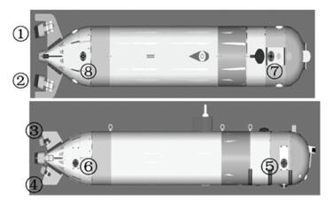
4 Application of Novel S-plane Controller 4.1 AUV PlatformAUV-X of Harbin Engineering University is the research object in this study. As shown in Fig. 1, it includes planning system, navigation system, basic motion control system, power system, acoustic vision system, optical vision and emergency response system, all of which are embedded into the AUV body.
|
Figure 1 Configuration of AUV-X |
The sensors equipped on the AUV are GPS for position measurement, Doppler velocity logger for speed measurement, optical fiber compass for attitude angle data, depth logger that measures the distance to the surface, altimeter that measures the distance to the bottom, image sonar and video camera. In addition, the inertial navigation system is also equipped for underwater dead reckoning. There are eight thrusters but no active rudder or fin. Two of the eight thrusters server as the horizontal main thrusters (one as the left main thruster① and the other as right main thruster②), with their axis 13°to that of the AUV-X. Another two thrusters server as the vertical main thrusters (one as the upper main thruster③ and the other as the subjacent main thruster④), with their axis 26° to that of the AUV-X. In addition, four conduit thrusters are used as the lateral thrusters (the bow lateral thruster⑤ and the stern lateral thruster⑥) and vertical thrusters (the bow vertical thruster⑦ and the stern vertical thruster⑧).The primary missions of the AUV cover pipeline detection, target detection and identification, long-distance high-speed motion as well as data collection, etc.
4.2 Control AlgorithmIn the presence of high-speed motion and with considerations of the significant coupling effect between the longitudinal velocity and the other degrees of freedom, the traditional S-plane controller is used to accumulate the longitudinal output to deal with the fast changes of the longitudinal velocity. As for the other degrees of freedom, the novel S-plane controller in this study is applied. Given to the influence of deviation and deviation change rate, this study makes reference to the traditional S-plane controller in the definition of the sliding mode surface in Eq. (15).
| $ \mathit{\boldsymbol{s = }}{k_1}\mathit{\boldsymbol{e + }}{k_2}\mathit{\boldsymbol{\dot e}} $ | (15) |
where
| $ \mathit{\boldsymbol{e = }}{\left[ {\begin{array}{*{20}{c}} {{u_d} - u} & {{y_d} - y} & {{z_d} - z} & {{\varphi _d} - \varphi } & {{\theta _d} - \theta } & {{\psi _d} - \psi } \end{array}} \right]^{\rm{T}}} $ |
It is noticeable that at the time of high-speed motion, speed control is typically conducted in longitude with position control carried out for the other degrees of freedom. The longitudinal control inputs are longitudinal velocity deviation and longitudinal acceleration, while the control inputs of the other degrees of freedom are position deviation and its change rate or angular deviation and its change rate.
| $ \begin{array}{l} {\mathit{\boldsymbol{K}}_1} = {\rm{diag}}\left( {{k_{11}},{k_{12}},{k_{13}},{k_{14}},{k_{15}},{k_{16}}} \right)\\ {\mathit{\boldsymbol{K}}_2} = {\rm{diag}}\left( {{k_{21}},{k_{22}},{k_{23}},{k_{24}},{k_{25}},{k_{26}}} \right) \end{array} $ |
The control model is as follows:
| $ \left\{ \begin{array}{l} {\mathit{\boldsymbol{f}}_\mathit{\boldsymbol{i}}} = \sum {{\mathit{\boldsymbol{K}}_{\mathit{\boldsymbol{si}}}}\mathit{\boldsymbol{f}}\left( {{\mathit{\boldsymbol{s}}_\mathit{\boldsymbol{i}}}} \right)} ,\;\;\;\;\;\;\;\;i = 1\\ {\mathit{\boldsymbol{f}}_\mathit{\boldsymbol{i}}} = {{\mathit{\boldsymbol{\hat R}}}_\mathit{\boldsymbol{i}}} + {\mathit{\boldsymbol{K}}_{si}}\exp \left( {{\varepsilon _i}{u^2}} \right)\mathit{\boldsymbol{f}}\left( {{\mathit{\boldsymbol{s}}_\mathit{\boldsymbol{i}}}} \right),i = 2 \cdots 6 \end{array} \right. $ | (16) |
where fi stands for the force and moment provided in each degree of freedom. si and
In view of the AUV's symmetric and slender body as shown in Fig. 1, the rolling motion is not taken into account. The thrusters are arranged as illustrated in Fig. 1. The forces provided by the left main thruster and the right main thruster are assumed to be Fthr1 and Fthr2, with the arm of force lthr1 and lthr2 and angle γ to the axis of the AUV. The forces provided by the upper main thruster and the subjacent main thruster are Fthr3 and Fthr4 , with the arm of force lthr3 and lthr4 and angle Θ to the axis of the AUV. The forces provided by the bow lateral thruster and the stern lateral thruster are Fthr5 and Fthr6 , with the arm of force lthr5 and lthr6 . And the forces provided by the bow vertical thruster and the stern vertical thruster are Fthr7 and Fthr8 , with the arm of force lthr7 and lthr8 . Fx, Fy and Fz are the forces provided in the surge, sway and heave directions while My and Mz are the moments in the pitch and yaw directions. Eq. (17) can be reached as follows.
| $ \left[ {\begin{array}{*{20}{c}} {{\mathit{\boldsymbol{F}}_x}}\\ {{\mathit{\boldsymbol{F}}_y}}\\ {{\mathit{\boldsymbol{F}}_z}}\\ {{\mathit{\boldsymbol{M}}_y}}\\ {{\mathit{\boldsymbol{M}}_z}} \end{array}} \right] = \left[ {\begin{array}{*{20}{c}} {\cos \gamma } & {\cos \gamma } & {\cos \mathit{\Theta }} & {\cos \mathit{\Theta }} & 0 & 0 & 0 & 0\\ { - \sin \gamma } & {\sin \gamma } & 0 & 0 & 1 & 1 & 0 & 0\\ 0 & 0 & { - \sin \mathit{\Theta }} & {\sin \mathit{\Theta }} & 0 & 0 & 1 & 1\\ 0 & 0 & { - {l_{{\rm{thr}}3}}} & {{l_{{\rm{thr}}4}}} & 0 & 0 & { - {l_{{\rm{thr}}7}}} & {{l_{\mathit{thr}8}}}\\ { - {l_{{\rm{thr}}1}}} & {{l_{{\rm{thr}}2}}} & 0 & 0 & {{l_{{\rm{thr}}5}}} & { - {l_{{\rm{thr}}6}}} & 0 & 0 \end{array}} \right]\left[ {\begin{array}{*{20}{c}} {{F_{{\rm{thr}}1}}}\\ {{F_{{\rm{thr}}2}}}\\ {{F_{{\rm{thr}}3}}}\\ {{F_{{\rm{thr}}4}}}\\ {{F_{{\rm{thr}}5}}}\\ {{F_{{\rm{thr}}6}}}\\ {{F_{{\rm{thr}}7}}}\\ {{F_{{\rm{thr}}8}}} \end{array}} \right] $ | (17) |
As shown in Eq. (17), the thrusters are redundant. For the purpose of simplified calculation, more constraints are required for thrust allocation in accordance with task requirements in practice.
In case of high-speed motion control ( > 0.8 m/s), the unsatisfactory force provided by the conduit thrusters in the sway direction often fails the desired sway motion condition. For this reason, motion control can be realized by adjusting the yaw angle, hence
| $ {F_y} = 0 $ | (18) |
Likewise, there exists considerable coupling effect between surge and heave motions upon high-speed control. Depth control is realized by adjusting the pitch angle and no force is provided in the vertical direction, hence
| $ {F_z} = 0 $ | (19) |
Considering the significant thrust reduction of conduit thrusters upon high-speed motion, the yaw and pitch are not controlled by the conduit thrusters for energy efficiency, hence
| $ \left\{ \begin{array}{l} {F_{{\rm{thr}}5}} \cdot {l_{{\rm{thr}}5}} - {F_{{\rm{thr}}6}} \cdot {l_{{\rm{thr}}6}} = 0\\ {F_{{\rm{thr7}}}} \cdot {l_{{\rm{thr}}7}} - {F_{{\rm{thr}}8}} \cdot {l_{{\rm{thr}}8}} = 0 \end{array} \right. $ | (20) |
The force required in surge direction is allocated after taking into account of the maximum force that can be provided by the main thrusters. When η is the ratio of the maximum force provided by the horizontal main thrusters and the vertical main thrusters, hence
| $ \left( {{F_{{\rm{thr}}1}} + {F_{{\rm{thr}}2}}} \right)\cos \gamma = \eta \left( {{F_{{\rm{thr}}3}} + {F_{{\rm{thr}}4}}} \right)\cos \mathit{\Theta } $ | (21) |
Eqs. (17)-(21) jointly lead to the force provided by each thruster for the purpose of velocity control upon high-speed motion.
In position control, the AUV proceeds in a slow and stable way and potent force can be provided by the conduit thrusters. Therefore, the constraints are added as follows. The upper main thruster and the subjacent main thruster are shutdown, namely Fthr3=Fthr4=0. The lateral force is provided by the bow lateral thruster and the stern lateral thruster. The longitudinal force and bow rolling moment are provided by the left main thruster and the right main thruster. The vertical force is provided by the bow vertical thruster and the stern vertical thruster. The pitch angle is not taken into consideration. In this way, Eq. (17) is simplified into Eq. (22).
| $ \left[ {\begin{array}{*{20}{c}} {{\mathit{\boldsymbol{F}}_x}}\\ {{\mathit{\boldsymbol{F}}_y}}\\ {{\mathit{\boldsymbol{F}}_z}}\\ {{\mathit{\boldsymbol{M}}_z}} \end{array}} \right] = \left[ {\begin{array}{*{20}{c}} {\cos \gamma } & {\cos \gamma } & 0 & 0 & 0 & 0\\ { - \sin \mathit{\Theta }} & {\sin \mathit{\Theta }} & 1 & 1 & 0 & 0\\ 0 & 0 & 0 & 0 & 1 & 1\\ { - {l_{{\rm{thr}}1}}} & {{l_{{\rm{thr}}2}}} & {{l_{{\rm{thr}}5}}} & { - {l_{{\rm{thr}}6}}} & 0 & 0 \end{array}} \right]\left[ {\begin{array}{*{20}{c}} {{\mathit{\boldsymbol{F}}_{{\rm{thr}}1}}}\\ {{\mathit{\boldsymbol{F}}_{{\rm{thr}}2}}}\\ {{\mathit{\boldsymbol{F}}_{{\rm{thr}}5}}}\\ {{\mathit{\boldsymbol{F}}_{{\rm{thr}}6}}}\\ {{\mathit{\boldsymbol{F}}_{{\rm{thr}}7}}}\\ {{\mathit{\boldsymbol{F}}_{{\rm{thr}}8}}} \end{array}} \right] $ | (22) |
Eqs. (23) and (24) are the constraints.
| $ {F_{{\rm{thr}}5}} \cdot {l_{{\rm{thr}}5}} - {F_{{\rm{thr}}6}} \cdot {l_{{\rm{thr}}6}} = 0 $ | (23) |
| $ {F_{{\rm{thr7}}}} \cdot {l_{{\rm{thr}}7}} - {F_{{\rm{thr}}8}} \cdot {l_{{\rm{thr}}8}} = 0 $ | (24) |
Eqs.(22)-(24) specify the force provided by each thruster for position control.
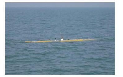
5 Test ResultsLongitudinal velocity control, heading control and depth control tests are carried out on the research object in sea trial. The sea trial condition is shown in Fig. 2. The parameters of longitudinal, heading and depth control are as follows. Ks1=100, k11=1.2, k21=0.6; Ks6=500, k16=0.6, k26=0.3; Ks3=100, k13=3.0, k23=1.5,
|
Figure 2 Experiment area for sea trial |
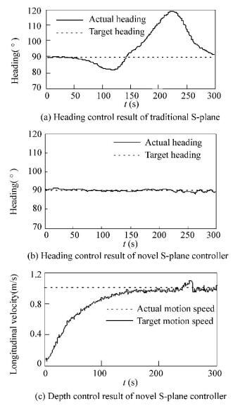
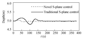
Figs. 3 and 4 respectively show the results of heading control and depth control at the time of high-speed (here 1.0 m/s) motion with traditional S-plane controller and the novel S-plane controller proposed in this study. In Fig. 3, the control results of traditional S-plane controller are shown in Fig. 3(a) while the results of the novel S-plane controller are shown in Figs. 3(b) and 3(c). As it is suggested in Fig. 3, buffeting begins as the motion speed gets closer to 0.8 m/s with the maximum deviation almost 27°. The controller is almost out of control. The instability in heading control, in turn, makes it difficult to achieve the expected longitudinal velocity. With the novel S-plane controller, heading control presents a deviation within ±3°and in the meantime, the motion speed is within the preset scope. Fig. 4 gives the contrast in depth control of the two controllers. With in 50-100 control periods (every 1 s), there is significant overshoot in depth control with the traditional S-plane controller. It is because the traditional S-plane controller eliminates the influence of residual buoyancy by way of continuous accumulation. In this period of time, however, the integration has become saturated. In contrast, the novel S-plane controller has taken the influence of residual buoyancy into account. Therefore, its control effect is greatly superior to that of the traditional S-plane controller.
|
Figure 3 Contrast of heading control result at time of high-speed motion |
|
Figure 4 Contrast of depth control result |
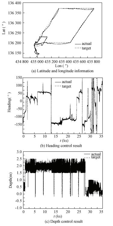
Fig. 5 shows the test results of an 80 km long-distance travel in sea trial. Fig. 5(a) shows the latitude and longitude data that is calculated by the navigation system. Fig. 5(b) provides the heading angle data, and the depth information is shown in Fig. 5(c). The 10-hour travel includes three parts, namely departure, parallelogram route of 2 km * 15 km and return. The velocity control is conducted during the long-distance travel while position control is carried out in the close range. For the departure and return, the target depth is 0.5 m for the safety of the AUV. During the long-distance travel, however, the target depth is 2.0 m and the AUV must come to the surface on a regular basis for GPS calibration and underwater navigation error correction. As it is suggested in Fig. 5, the motion control is quite satisfying on the whole. Nevertheless, the current is torrential in some areas since the test is conducted in the open sea. This challenges the AUV's ability, which accounts for the deviation between the actual route and the target route. Also, the changes of seabed topography and the influence of vertical flow result in occasional failure of some of the basic sensors such as Doppler velocity logger. There exists a deviation of 0.5 m in the depth control, but generally, the control precision can satisfy the needs of long-distance travel in practice.
|
Figure 5 Results of long distance navigation trial |
6 Conclusions
Based on a thorough analysis of the mathematical model of the AUV, a novel S-plane controller established on sliding mode control is proposed in this study. The simple structure and easily adjustable parameters of the traditional S-plane controller are kept in the novel controller and improvements are made on its weakness in integral saturation which is very likely to happen. The difficulty in heading control and slow vertical response at the time of high-speed motion is solved. Also, the stability analysis of the novel S-plane controller is carried out with Lyapunov function to prove that the stability of the novel design can meet the requirements. Thrust allocation method based on constraints is introduced. Finally, the novel S-plane controller is applied to heading and depth control of AUV-X with satisfying control effect achieved.
The novel S-plane controller established on sliding mode control is developed with deep analysis of the AUV motion model, but it is easy to realize since the controller only requires preliminary knowledge of the AUV model contents such as residual buoyancy and restoring moment. There is significant coupling effect among the degrees of freedom in the AUV operation, which results in the control failure of traditional S-plane controller at the time of high-speed motion. The novel S-plane controller proposed in this study gives considerations to the coupling influence of longitudinal velocity on the other degrees of freedom and solves the problem of control failure. It is open to further research since the coupling effect among the other degrees of freedom requires deeper studies.
| [1] |
Kim D W. Tracking of REMUS autonomous underwater vehicles with actuator saturations.
Automatic, 2015, 58: 15-21.
DOI:10.1016/j.automatica.2015.04.029 ( 0) 0)
|
| [2] |
Meenakshi S, Sambhunath N, Sankar N S. Energy efficient trajectory tracking controller for underwater applications: a robust approach.
Aquatic Procedia, 2015, 4: 571-578.
DOI:10.1016/j.aqpro.2015.02.074 ( 0) 0)
|
| [3] |
Hossein N E, Vahid A, Mohammad D. A time delay controller included terminal sliding mode and fuzzy gain tuning for underwater vehicle-manipulator system.
Ocean Engineering, 2015, 107: 97-107.
DOI:10.1016/j.oceaneng.2015.07.043 ( 0) 0)
|
| [4] |
Shafiei M H, Binazadeh T. Application of neural network and genetic algorithm in identification of a model of a variable mass underwater vehicle.
Ocean Engineering, 2015, 96: 173-180.
DOI:10.1016/j.oceaneng.2014.12.021 ( 0) 0)
|
| [5] |
Kim D, Choi H S, Kim J Y, et al. Trajectory generation and sliding-mode controller design of an underwater vehicle-manipulator system with redundancy.
International Journal of Precision Engineering and Manufacturing, 2015, 16(7): 1561-1570.
DOI:10.1007/s12541-015-0206-y ( 0) 0)
|
| [6] |
Moralesa R, Sira-Ramírezb H, Somolinosc J A. Linear active disturbance rejection control of the hovercraft vessel model.
Ocean Engineering, 2015, 96: 100-108.
DOI:10.1016/j.oceaneng.2014.12.031 ( 0) 0)
|
| [7] |
Khodayari M H, Balochian S. Modeling and control of autonomous underwater vehicle (AUV) in heading and depth attitude via self-adaptive fuzzy PID.
Journal of Marine Science and Technology, 2015, 20(3): 559-578.
DOI:10.1007/s00773-015-0312-7 ( 0) 0)
|
| [8] |
Tran N H, Choi H S, Bae J H, et al. Design, control and implementation of a new AUV platform with a mass shifter mechanism.
International Journal of Precision Engineering and Manufacturing, 2015, 16(7): 1599-1608.
DOI:10.1007/s12541-015-0210-2 ( 0) 0)
|
| [9] |
Joo M G, Qu Z. An autonomous underwater vehicle as an underwater glider and its depth control.
International Journal of Control, Automation and Systems, 2015, 13(7): 1212-1220.
DOI:10.1007/s12555-014-0252-8 ( 0) 0)
|
| [10] |
Behdad G, Saeed R N. Nonlinear suboptimal control of fully coupled non-affine six-DOF autonomous underwater vehicle using the state-dependent Riccati equation.
Ocean Engineering, 2015, 96: 248-257.
DOI:10.1016/j.oceaneng.2014.12.032 ( 0) 0)
|
| [11] |
Burguera A, Bonin-Font F, Oliver G. Trajectory-based visual localization in underwater surveying missions.
Sensors, 2015, 15: 1708-1735.
DOI:10.3390/s150101708 ( 0) 0)
|
| [12] |
Mai B L, Choi H S, You S S, et al. Time optimal trajectory design for unmanned underwater vehicle.
Ocean Engineering, 2014, 89: 69-81.
DOI:10.1016/j.oceaneng.2014.06.019 ( 0) 0)
|
| [13] |
Mohan S, Kim J. Coordinate motion control in task space of an autonomous underwater vehicle-manipulator system.
Ocean Engineering, 2015, 104: 155-167.
DOI:10.1016/j.oceaneng.2015.05.011 ( 0) 0)
|
| [14] |
Kim D W, Lee H J, Kim M H. Robust sampled-data fuzzy control of nonlinear systems with parametric uncertainties: its application to depth control of autonomous underwater vehicles.
International Journal of Control, Automation and Systems, 2012, 10(6): 1164-1172.
DOI:10.1007/s12555-012-0611-2 ( 0) 0)
|
| [15] |
Mukherjee K, Kar I N, Bhatt R K P. Region tracking based control of an autonomous underwater vehicle with input delay.
Ocean Engineering, 2015, 99: 107-114.
DOI:10.1016/j.oceaneng.2015.02.006 ( 0) 0)
|
| [16] |
Azis F A, Aras M S M, Rashid M Z A. Problem identification for underwater romotely operated vehicle (ROV): A case study.
International Journal of Control, Engineering Procedia, 2012, 4: 554-560.
DOI:10.1016/j.proeng.2012.07.211 ( 0) 0)
|
| [17] |
Maurizio P, Gary R, Daniel J S. Tracking and formation control of multiple autonomous agents: a two-level consensus approach.
Automatic, 2007, 43: 1318-1328.
DOI:10.1016/j.automatica.2007.01.004 ( 0) 0)
|
| [18] |
Bessaa W M, Dutrab M S, Kreuzerc E. An adaptive fuzzy sliding mode controller for remotely operated underwater vehicles.
Robotics and Autonomous Systems, 2010, 58(1): 16-26.
DOI:10.1016/j.robot.2009.09.001 ( 0) 0)
|
| [19] |
Lionel L, Didik S. Nonlinear path-following control of an AUV.
Ocean Engineering, 2007, 34: 1734-1744.
DOI:10.1016/j.oceaneng.2006.10.019 ( 0) 0)
|
| [20] |
Bagheri A, Moghaddam J J. Simulation and tracking control based on neural-network stategy and sliding-mode control for underwater remotely operated vehicle.
Neurocomputing, 2009, 72(7-9): 1934-1950.
DOI:10.1016/j.neucom.2008.06.008 ( 0) 0)
|
| [21] |
Ishaque K, Abdullas S S, Ayob S M, et al. A simplified approach to design fuzzy logic controller for an underwater vehicle.
Ocean Engineering, 2011, 38(1): 271-284.
DOI:10.1016/j.oceaneng.2010.10.017 ( 0) 0)
|
| [22] |
Javadi J, Bagheri A. An adaptive neuron-fuzzy sliding mode based genetic algorithm control system for underwater remotely operated vehicle.
Expert Systems with Applications, 2010, 37: 647-660.
DOI:10.1016/j.eswa.2009.06.015 ( 0) 0)
|
| [23] |
Bagheri A, Karimi T, Amanifard N. Tracking performance control of a cable communicated underwater vehicle using adaptive neural network controllers.
Applied Soft Computing, 2010, 10: 908-918.
DOI:10.1016/j.asoc.2009.10.008 ( 0) 0)
|
| [24] |
Wu B, Song J L. Hybrid adaptive fuzzy control for a class of nonaffine nonlinear system.
Electric Machines and Control, 2013, 17(5): 51-57.
( 0) 0)
|
| [25] |
Sun Yusan, Wan Lei, Gan Yong, et al. Design of motion control of dam safety inspection underwater vehicle.
Journal of Center South University, 2012, 19(3): 1522-1529.
DOI:10.1007/s11771-012-1171-6 ( 0) 0)
|
| [26] |
Wang Jianguo, Sun Yushan. Research on motion control of autonomous underwater vehicle.
Chinese High Technology Letters, 2010, 20(11): 1156-1161.
( 0) 0)
|
| [27] |
Xi Bin, Chen Jie, Peng Zhihong. Intelligent Optimized Control: Overview and Prospect.
Acta Automatica Sinica, 2013, 39(11): 1831-1834.
DOI:10.3724/SP.J.1004.2013.01831 ( 0) 0)
|
| [28] |
Li Ye, Pang Yongjie, Zhang Lei. Semi-physical simulation system of AUV pipeline tracking.
Journal of Center South University, 2012, 19(3): 2468-2476.
( 0) 0)
|
| [29] |
Zhu Daqi, Li Xin, Yan Mingzhong. Task assignment algorithm of multi-AUV based on self-organizing map.
Control and Decision, 2012, 27(8): 1201-1205.
( 0) 0)
|
 2017, Vol. 24


