Shakedown should be conducted for a structure with elastic-plastic material under repeated loads to prevent low-cycle fatigue and progressive plastic deformation failure. The determination of structural shakedown behavior under variable loading is important in structural evaluation and design. Complete analytical shakedown solutions are solved for some relatively simple structure. For complex structures and boundary conditions, the solutions of the shakedown limit load are calculated employing finite element numerical methods. This leads to develop numerical method by applying shakedown theorem. The classic shakedown theorems are the static (Melan) shakedown theorem[1] and kinematic shakedown theorem[2]. Melan's shakedown theorem is particularly popular as it leads to conservative lower-bound solution which is desirable in engineering field.
Melan's theorem uses the statically admissible residual stress field to check structural shakedown behavior. For simplicity, it neglects material hardening and adopts an elastic-perfectly plastic material model. The geometric effect, inertia and viscous forces are all neglected. The static shakedown theorem in its original formulation is only valid for proportional loading and not combined loading. To address situations that are more realistic, the classic theorems have been extensively extended; e.g., the extensions for considering a combined loading with a constant load and cyclic load[3] and extensions for considering the geometry effect[4] and strain hardening[5]. The methods that apply Melan's theorem solve the shakedown limit load by finding the optimal residual stress field. It is thus always the case that a fictitious statically admissible residual stress field is constructed, and the optimal stress field is then searched. Most of the methods are reformulated to mathematical programming problems. To improve the computational efficiency and accuracy and to overcome potential dimension obstacles, great efforts have been made to construct statically admissible residual stress fields and to develop mathematical programming algorithms[6-8]. Among these programming algorithms, the interior-point algorithm has been well developed to solve problems of large-scale engineering structures, multidimensional loading spaces, and kinematical hardening material. There are also methods that avoid mathematical programming. Nonlinear Superposition Method[9] and a simplified technique[10] construct the statically admissible stress field by performing elastic analysis and elastic-plastic analysis, respectively. The statically admissible stress field is constructed by superposing the results of the two analyses. The shakedown limit load is then determined by the superposition of stress fields[10]. These methods have been applied to a number of practical components[11-12]. Another method is to apply iterative elastic techniques; e.g., the GLOSS R-Node method[13], the Elastic Compensation Method[14], and the Linear Matching Method[15-16]. Among these, the Linear Matching Method has been developed to be suitable for practical engineering applications involving a complicated thermo-mechanical load history[15], and developed into a software tool of an Abaqus computer aided engineering plug-in with graphical user interfaces[16]. Another new numerical procedure based on residual stress decomposition with a Fourier series has also been proposed and applied to thermomechanical loading[17-18].
In many engineering applications, structures are subjected to combined loading with constant and cyclic loads. It needs to clarify the influence of combined loading in structural shakedown for structural design and evaluation. In general, specific shakedown limit loads are obtained employing the numerical method above or the analytical method. As an example, the shakedown analysis of a hollow tensile specimen subjected to combined constant tension and cyclic torsion has been conducted employing the interior-point method[7], the shakedown limit load of a square plate with a central small hole subjected to a combined constant horizontal tensile stress and cyclic vertical tensile stress has been calculated employing the Nonlinear Superposition Method[9]. The shakedown limit loads of a 90° mitred pipe bends subjected to steady internal pressure and cyclic bending moments[19-20], a functionally graded rotating disk subjected to cyclic temperature gradient loading and a constant rotational speed are also been developed by numerical methods[21].
However the general effect rules of the combined loading in structural shakedown have not yet been given. The general analytical relationship between combined loads and the shakedown limit load is not clear. The present paper investigates the general effect of the combination loading on structural shakedown behavior employing an analytic method. Polizzotto's extended static shakedown theory is applied. The stress field in equilibrium with the external constant load required in Polizzotto's extended theorem for the lower-bound shakedown analysis is constructed. The shakedown condition of the structure is then derived. The elastic shakedown of the structure under combined loading is discussed through analytical analysis, and the general analytical solution of the shakedown limit load is derived. The general effect of the combined loading on the shakedown limit load is presented. The general result is applied to a hollow tension specimen under constant tension and alternating torsion and a plate with a central hole under constant and cyclic tension. The results are compared with solutions from the literature.
2 Static Shakedown Theorem 2.1 Classic Static Shakedown TheoremIn many situations, it is useful to employ the fictitious perfectly elastic structure of the actual structure with only its elastic properties. In static shakedown theory, the fictitious perfectly elastic structure is used to develop the reference elastic stress field. Melan's classic static shakedown theorem states the following[1].
For a given cyclic load set, a structure made of elastic-perfectly plastic material will shake down if a time-independent self-equilibrium residual stress field can be found such that the combination of the reference elastic stress and residual stress satisfies the condition[1, 9]
| $ {f_Y}\left[ {\mathit{\boldsymbol{\sigma }}_{ij}^{\rm{e}}\left( {x,t} \right) + \mathit{\boldsymbol{\sigma }}_{ij}^{\rm{r}}\left( x \right),{\sigma _Y}} \right] \le 0 $ |
for any loads in the loading domain and anywhere in the structure, where fY(σij, σY)=0 is the yield condition and σije(x, t) is the reference elastic stress field. σijr(x) is the self-equilibrium time-independent residual stress field and σY is the yield stress of the material. It is obvious that Melan's theorem is not suitable for combined loading with constant and cyclic loads.
2.2 Extended Static Shakedown TheoremIn reality, many engineering structures are subjected to a combined loading with constant and cyclic loads. The combined loads can be denoted by P(t) and expressed as
| $ P\left( t \right) = {P_0} + {P_{\rm{c}}}\left( t \right) $ |
where P0 is the constant load and Pc(t) is the cyclic load with peak cyclic load Pcmax and valley cyclic load Pcmin; i.e., Pc(t)∈[Pcmin, Pcmax].
Polizzotto's extended static theorem makes use of time-independent stress fields, which are in static equilibrium with the external constant load, instead of the self-equilibrium residual stress field used in Melan's theorem. Polizzotto's extended static shakedown theorem for the combined loading P(t) states the following[3, 9].
For elastic-perfectly plastic structures, the necessary and sufficient condition for elastic shakedown to occur under the combined cyclic and constant loads is that a time-independent stress field σija(x), which is in equilibrium with the external constant load P0, can be found such that the combination of the reference elastic stress of the fictitious perfectly elastic structure for the cyclic load and the stress σija(x) does not violate yield condition[3, 9]:
| $ {f_Y}\left[ {\mathit{\boldsymbol{\sigma }}_{ij}^{\rm{e}}\left( {x,t} \right) + \mathit{\boldsymbol{\sigma }}_{ij}^{\rm{a}}\left( x \right),{\sigma _Y}} \right] \le 0 $ |
The shakedown limit load can then be searched for by searching the stress field σija(x).
3 Shakedown Analysis of the Structure Under Combined LoadingBecause the stress distribution of the structure is not uniform, only the critical points with high stress should be checked to determine the shakedown behavior of the structure. For simplicity, only one structural critical point is discussed in the following to illustrate the analysis process.
3.1 Shakedown Condition and Its Analytical AnalysisFor shakedown analysis under a combined load P(t), it is reasonable to assume that, when the cyclic load Pc(t) reaches its peak value (i.e., P(t)=P0+Pcmax), the structure is in an elastic-plastic state. Then, according to Polizzotto's theorem, a stress field σija(x) in equilibrium with the external constant load P0 is constructed as
| $ \mathit{\boldsymbol{\sigma }}_{ij}^{\rm{a}}\left( x \right) = \mathit{\boldsymbol{\sigma }}_{ij}^{\rm{0}}\left( x \right) - \mathit{\boldsymbol{\sigma }}_{ij\max }^{\rm{e}}\left( x \right) $ | (1) |
where σij0(x) is the elastic-plastic stress field for the combined load at which the cyclic load reaches its peak (i.e., P0+Pcmax) and σijmaxe(x) is the reference elastic stress field of the peak cyclic load Pcmax. The combination of the reference elastic stress of the cyclic load and the stress σija(x) should then not violate the yield condition anywhere or at any time, and the shakedown conditions of the structure based on the stress constructed with Eq. (1) can thus be concluded as
| $ {f_Y}\left[ {\mathit{\boldsymbol{\sigma }}_{ij\max }^{\rm{e}}\left( x \right) + \mathit{\boldsymbol{\sigma }}_{ij}^{\rm{a}}\left( x \right),{\sigma _Y}} \right] \le 0 $ | (2) |
| $ {f_Y}\left[ {\mathit{\boldsymbol{\sigma }}_{ij\min }^{\rm{e}}\left( x \right) + \mathit{\boldsymbol{\sigma }}_{ij}^{\rm{a}}\left( x \right),{\sigma _Y}} \right] \le 0 $ | (3) |
where σijmine(x) is the reference elastic stress field of the valley cyclic load Pcmin.
Substituting Eq. (1) into Eq. (2) yields
| $ {f_Y}\left( {\mathit{\boldsymbol{\sigma }}_{ij}^0\left( x \right),{\sigma _Y}} \right) \le 0 $ | (4) |
Because the structure is assumed to be in an elastic-plastic state, the elastic-plastic stress field σij0(x) naturally satisfies Eq. (4).
Substituting Eq. (1) into Eq. (3) yields
| $ {f_Y}\left[ {\boldsymbol{\sigma }_{ij\min }^{\rm{e}}\left( x \right) + \boldsymbol{\sigma }_{ij}^0\left( x \right) - \boldsymbol{\sigma }_{ij\max }^{\rm{e}}\left( x \right),{\sigma _Y}} \right] \le 0 $ | (5) |
It follows that
| $ {f_Y}\left[ {\boldsymbol{\sigma }_{ij}^0\left( x \right) - \boldsymbol{\sigma }_{ij}^{\rm{E}}\left( x \right),{\sigma _Y}} \right] \le 0 $ | (6) |
where σijE(x)= σijmaxe(x)-σijmine(x) is the reference elastic stress field of the scope of the cyclic load Pcmax-Pcmin. The shakedown condition of the structure under the combined constant and cyclic load is thus expressed as Eq. (6). The shakedown limit load can be obtained by searching for the maximum load that satisfies Eq. (6).
Materials are assumed to follow the von Mises criterion. The yield condition fY(σij, σY)=0 can be written as
| $ {f_Y}\left( {{\boldsymbol{\sigma }_{ij}},{\sigma _Y}} \right) = 1/2\left( {{\boldsymbol{\sigma }_{ij}}{\boldsymbol{\sigma }_{ij}} - 3\sigma _m^2} \right) - \sigma _Y^2/3 = 0 $ |
where σij is elastic-plastic stress of the structure, σm is the average value of the three normal stress components of σij; i.e., the hydrostatic stress, σm=(σ1+σ2+σ3)/3. The left term of Eq. (6) can then be expressed as
| $ \begin{array}{l} {f_Y}\left[ {\boldsymbol{\sigma }_{ij}^0 - \boldsymbol{\sigma }_{ij}^{\rm{E}}\left( x \right),{\sigma _Y}} \right] = \\ \;\;\;\;1/2\left[ {\left( {\boldsymbol{\sigma }_{ij}^0 - \boldsymbol{\sigma }_{ij}^{\rm{E}}} \right)\left( {\boldsymbol{\sigma }_{ij}^0 - \boldsymbol{\sigma }_{ij}^{\rm{E}}} \right) - 3\left( {\sigma _m^0 - } \right.} \right.\\ \;\;\;\;\left. {{{\left. {\sigma _m^{\rm{E}}} \right)}^2}} \right] - \sigma _Y^2/3 = 1/2\left[ {\boldsymbol{\sigma }_{ij}^0\boldsymbol{\sigma }_{ij}^0 - 3{{\left( {\sigma _m^0} \right)}^2} - \left( {2\boldsymbol{\sigma }_{ij}^0 - } \right.} \right.\\ \;\;\;\;\left. {\left. {\boldsymbol{\sigma }_{ij}^{\rm{E}}} \right)\boldsymbol{\sigma }_{ij}^{\rm{E}} + 3\left( {2\sigma _m^0 - \sigma _m^{\rm{E}}} \right)\sigma _m^{\rm{E}}} \right] - \sigma _Y^2/3 \end{array} $ | (7) |
where σm0 and σmE are the hydrostatic stresses of σij0 and σijE, respectively. As it is assumed that the structure is in an elastic-plastic state under P0+Pcmax, the critical point of the structure reaches a plastic state. The elastic-plastic stress σij0 thus satisfies the yield condition
| $ {f_Y}\left( {\boldsymbol{\sigma }_{ij}^0,{\sigma _Y}} \right) = 1/2\left[ {\boldsymbol{\sigma }_{ij}^0\boldsymbol{\sigma }_{ij}^0 - 3{{\left( {\sigma _m^0} \right)}^2}} \right] - {\left( {{\sigma _Y}} \right)^2}/3 = 0 $ | (8) |
where σm0 is the hydrostatic stress of σij0.
Substituting Eq. (8) into Eq. (7) yields
| $ \begin{array}{l} {f_Y}\left( {\boldsymbol{\sigma }_{ij}^0 - \boldsymbol{\sigma }_{ij}^{\rm{E}},{\sigma _Y}} \right) = {f_Y}\left( {\boldsymbol{\sigma }_{ij}^0,{\sigma _Y}} \right) - 1/2\left( 2{\boldsymbol{\sigma }_{ij}^0 - \boldsymbol{\sigma }_{ij}^{\rm{E}}} \right)\boldsymbol{\sigma }_{ij}^{\rm{E}} + \\ \;\;\;\;\;3/2\left( {2\sigma _m^0 - \sigma _m^{\rm{E}}} \right)\sigma _m^{\rm{E}} = - 1/2\left( 2{\boldsymbol{\sigma }_{ij}^0 - \boldsymbol{\sigma }_{ij}^{\rm{E}}} \right)\boldsymbol{\sigma }_{ij}^{\rm{E}} + \\ \;\;\;\;\;3/2\left( {2\sigma _m^0 - \sigma _m^{\rm{E}}} \right)\sigma _m^{\rm{E}} \end{array} $ | (9) |
According to the generalized Hooke law,
| $ \boldsymbol{\sigma }_{ij}^{\rm{E}} = 2G\boldsymbol{\varepsilon }_{ij}^{\rm{E}} + \lambda \varepsilon _v^{\rm{E}}{\delta _{ij}} $ | (10) |
| $ \sigma _m^{\rm{E}} = {\rm{K}}\varepsilon _{\rm{v}}^{\rm{E}} $ | (11) |
where
| $ \lambda = \mu E/\left[ {\left( {1 + \mu } \right)\left( {1 - 2\mu } \right)} \right] $ | (12) |
| $ K = E/3\left( {1 - 2\mu } \right) $ | (13) |
| $ G = E/2\left( {1 + \mu } \right) $ | (14) |
Here εijE is the elastic strain corresponding to σijE, εvE is the corresponding volumetric strain and the sum of the three principle strains of εijE; i.e., ε1E+ε2E+ε3E.δij is the unit tensor. If i = j, then δij=1. If i ≠ j, then δij=0. E is the elastic modulus, and μ is the Poisson ratio, and G is the shear modulus. Substituting Eqs. (10)-(14) into Eq. (9), we obtain
| $ \begin{array}{l} {f_Y}\left( {\boldsymbol{\sigma }_{ij}^0 - \boldsymbol{\sigma }_{ij}^{\rm{E}},{\sigma _Y}} \right) = - G\left( 2{\boldsymbol{\sigma }_{ij}^0 - \boldsymbol{\sigma }_{ij}^{\rm{E}}} \right)\boldsymbol{\varepsilon }_{ij}^{\rm{E}} + G\left( {2\sigma _m^0 - } \right.\\ \;\;\;\;\;\;\;\;\;\;\left. {\sigma _m^{\rm{E}}} \right)\varepsilon _v^{\rm{E}} \end{array} $ | (15) |
According to elastic-plastic theory,
| $ {\boldsymbol{\sigma }_{ij}} = {{\boldsymbol{\sigma '}}_{ij}} + {\sigma _m}{\delta _{ij}} $ | (16) |
| $ \boldsymbol{\varepsilon }_{ij}^{\rm{E}} = \boldsymbol{\varepsilon }_{ij}^{{\rm{E'}}} + \varepsilon _m^{\rm{E}}{\delta _{ij}} $ | (17) |
where εijE′ is the deviatoric stress of εijE. εmE is the average strain of the three principal strain components of εijE; i.e., εmE=(ε1E+ε2E+ε1E)/3. Substituting the expressions in Eqs. (16) and (17) into Eq. (15) yields
| $ {f_Y}\left( {\boldsymbol{\sigma }_{ij}^0 - \boldsymbol{\sigma }_{ij}^{\rm{E}},{\sigma _Y}} \right) = - G\left( {2\boldsymbol{\sigma }_{ij}^{0'} - \boldsymbol{\sigma }_{ij}^{{\rm{E'}}}} \right)\boldsymbol{\varepsilon }_{ij}^{{\rm{E'}}} $ | (18) |
where σij0′ is the deviatoric stress of σij0 and σijE' is the deviatoric stress of σijE. Eq. (18) is the expression of the left term of Eq. (6) for the critical point. Substituting the expression in Eq. (18) into Eq. (6), the shakedown condition of the structure is obtained as
| $ - G\left( {2\boldsymbol{\sigma }_{ij}^{0'} - \boldsymbol{\sigma }_{ij}^{{\rm{E'}}}} \right)\boldsymbol{\varepsilon }_{ij}^{{\rm{E'}}} \le 0 $ | (19) |
For the structure under combined loading in the shakedown state, the shakedown limit load is the maxium range of the cyclic load for a given constant load. The shakedown limit load can then be expressed as [PcminS, PcmaxS], where PcmaxS and PcminS are the peak and valley of the shakedown limit load respectively, PcmaxS-PcminS is the scope of the shakedown limit load.
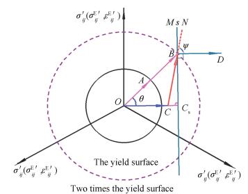
In a coordinate system on the π plane, vectors are used to represent the deviatoric stress field σ ij′, σijE′ and the deviatoric strain field εijE′, as illustrated in Fig. 1. The solid concentric circle is the yield curve. The radius of the dotted concentric circle is twice that of the solid circle.
|
Figure 1 Analytical analysis of the shakedown condition for θ∈(0, 90°) |
We set
| $ {f_Y}\left( {\boldsymbol{\sigma }_{ij}^0 - \boldsymbol{\sigma }_{ij}^{\rm{E}},{\sigma _Y}} \right) = - G \cdot \overrightarrow {\boldsymbol{CB}} \cdot \overrightarrow {\boldsymbol{BD}} $ | (20) |
Given that G>0, the sign of fY(σij0-σijE, σY) can be determined by the angle ψ between the vectors
By analyzing the geometric relationship in Fig. 1, it is clear that the value of ψ depends on θ and |
The situation that θ∈(0°, 90°) is illustrated in Fig. 1. By point B, line s running perpendicular to vectors
| $ \left| {\overrightarrow {\boldsymbol{OC}} } \right| \le \left| {\overrightarrow {\boldsymbol{O}{\boldsymbol{C}_s}} } \right| $ | (21) |
From the geometry,
| $ \left| {\overrightarrow {\boldsymbol{O}{\boldsymbol{C}_s}} } \right| = \left| {\overrightarrow {\boldsymbol{OB}} } \right|\cos \theta $ | (22) |
Substituting Eq. (22) into Eq. (21), we obtain
| $ \left| {\overrightarrow {\boldsymbol{OC}} } \right| \le \left| {\overrightarrow {\boldsymbol{OB}} } \right|\cos \theta $ | (23) |
According to
| $ \overline {\boldsymbol{\sigma }_{ij}^{{\rm{E'}}}} \le 2{\delta _Y}\cos \theta $ | (24) |
where
| $ {P_{{\rm{cmax}}}} - {P_{{\rm{cmin}}}} \le 2P\left( {{\delta _Y}} \right)\cos \theta $ | (25) |
where P(δY) is the load under which the equivalent stress of the reference elastic stress is equal to the radius of the yield surface in the principal stress space. For a perfectly elastic-plastic material structure,
| $ P\left( {{\delta _Y}} \right) = P_{\rm{c}}^{\rm{e}} $ | (26) |
where Pce is the elastic limit load of the actual structure subjected to only the cyclic load Pc, which is referred to as the elastic limit load of only the cyclic load. Substituting Eq. (26) into Eq. (25), we obtain
| $ {P_{{\rm{cmax}}}} - {P_{{\rm{cmin}}}} \le 2P_{\rm{c}}^{\rm{e}}\cos \theta $ | (27) |
The shakedown limit load thus satisfies
| $ P_{{\rm{cmax}}}^{\rm{s}} - P_{{\rm{cmin}}}^{\rm{s}} = 2P_{\rm{c}}^{\rm{e}}\cos \theta $ | (28) |
It is concluded that the structural shakedown behavior is affected by the scope of the cyclic load Pcmax-Pcmin and the angle θ in this case. The value and direction of the constant load affect the structural shakedown behavior through the angle θ. Once θ is specified, the shakedown behavior depends on the scope of the cyclic load. If the cyclic load satisfies Eq. (27), the structure is shakedown. Because θ∈(0°, 90°), it follows that 0 < cos θ < 1, and the scope of the shakedown limit load PcmaxS-PcminS is thus smaller than twice the elastic limit load of only the cyclic load. If Pcmin=0, then the peak of the shakedown limit load satisfies PcmaxS=2Pcecos θ.
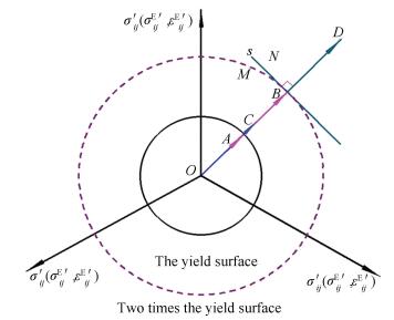
The situation that θ=0° is illustrated in Fig. 2. By point B, line s that runs perpendicular to vectors
|
Figure 2 Analytical analysis of the shakedown condition for θ=0° |
| $ \overline {\boldsymbol{\sigma }_{ij}^{{\rm{E'}}}} \le 2{\delta _Y} $ | (29) |
The shakedown condition of the cyclic load in this case is
| $ {P_{{\rm{cmax}}}} - {P_{{\rm{cmin}}}} \le 2P_{\rm{c}}^{\rm{e}} $ | (30) |
The scope of the shakedown limit load therefore satisfies
| $ P_{{\rm{cmax}}}^S - P_{{\rm{cmin}}}^S = 2P_{\rm{c}}^{\rm{e}} $ | (31) |
In particular, if Pcmin=0, the peak of the shakedown limit load Pcmax is twice the elastic limit load of only the cyclic load; i.e., PcmaxS=2Pce.
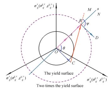
The situation that θ=90° is illustrated in Fig. 3. By point B, line s that runs perpendicular to vectors
|
Figure 3 Analytical analysis of the shakedown condition for θ=90° |
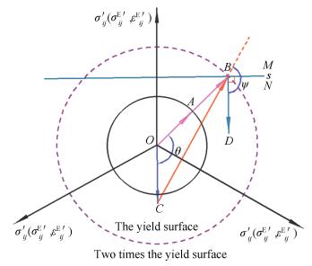
The situation that θ∈(90°, 180°) is illustrated in Fig. 4. Because ψ>90°, it follows that fY(σij0-σijE, σY)>0 always holds. The situation that θ=180° is illustrated in Fig. 5. It is clear that point C can be only located within the half-space N, and ψ=180° and fY(σij0-σijE, σY)>0 always holds.
|
Figure 4 Analytical analysis of the shakedown condition for θ∈(90°, 180°) |

|
Figure 5 Analytical analysis of the shakedown condition for θ∈180° |
Therefore, if θ∈[90, 180°], the structure will not reach shakedown under the combined loading. θ∈[90, 180°] means that the constant load controls the stress state in the structure. The shakedown limit is no longer the major factor affecting structural safety. The major factor affecting structural safety is the plastic limit state. The safety load of the structure should be evaluated using the plastic limit load rather than the shakedown limit load.
4 DiscussionAs examples, two structures under combined loading are presented and analyzed.
4.1 Hollow Tension SpecimenA hollow tension specimen is subjected to alternating torsion with zero mean shear stress, such that -τmin=τmax, and a constant tensile stress, σ>0. The geometry of the specimen is given in Fig. 6. For this problem, the shakedown limit load of the shear stress given in Ref. [8] is

|
Figure 6 Geometry of the hollow tension specimen |
| $ \sqrt 3 \tau _{\max }^S = \sqrt {\sigma _Y^2 - {\sigma ^2}} $ | (32) |
For the specimen with an elastic-perfectly plastic material model under only cyclic torsion, it is clear that the shear stresses reach the maximum value at the outer radius, and the elastic limit of the shear stress load τmaxe satisfies
| $ \sqrt 3 \tau _{\max }^{\rm{e}} = {\sigma _Y} $ | (33) |
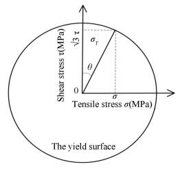
Because the angle between the shear stress τ and tensile stress σ is a right angle, as shown in Fig. 7, the angle θ between the stress of the combined loading with the peak cyclic torsion load and the constant tensile load and the reference elastic stress of the cyclic torsion load in this problem is θ∈[0, 90°]. If merely cyclic torsion is applied to the specimen, θ=0. If merely constant tension is applied to the specimen, θ=90°.
|
Figure 7 Shear stress and tensile stress in the stress space |
If θ∈(0°, 90°), according to Eq.(28), the shakedown limit load should satisfy
| $ \tau _{\max }^S - \tau _{\min }^S = 2\tau _{\max }^{\rm{e}}\cos \theta $ | (34) |
Substituting -τmin=τmax into Eq. (34) yields
| $ \tau _{\max }^S = \tau _{\max }^{\rm{e}}\cos \theta $ | (35) |
Substituting Eq. (33) into Eq. (35) yields
| $ \sqrt 3 \tau _{\max }^S = \sqrt 3 \tau _{\max }^{\rm{e}}\cos \theta = {\sigma _Y}\cos \theta $ | (36) |
If θ=0°, according to Eqs. (31) and (33) and -τmin=τmax, the shakedown limit load of the shear stress satisfies
| $ \sqrt 3 \tau _{\max }^S = \sqrt 3 \tau _{\max }^e = {\sigma _Y} $ | (37) |
If θ=90°, according to the analysis results presented in Section 4, the safety load of the tensile stress is the plastic limit load in this case.
Because the angle between the shear stress and tensile stress is a right angle, θ is thus shown in Fig. 7, and it is clear that Eq. (32) is equivalent to Eqs. (36) and (37). Therefore, the result in Ref.[8] is consistent with the analytical analysis results of the present paper.
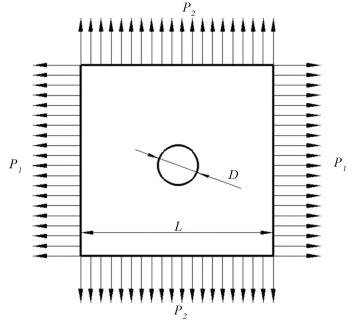
4.2 Square Plate with a Central HoleThe second example is a square plate with a central hole under combined loading with cyclic and constant loads. Fig. 8 is a schematic diagram of the plate and applied loads. The horizontal stress P1 is assumed to be constant, and the vertical stress P2 is assumed to vary cyclically between zero and its corresponding peak value; i.e., P2∈[0, P2max].
|
Figure 8 Schematic of the square plate with a central hole |
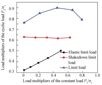
In Ref. [9], shakedown was analyzed employing the Nonlinear Superposition Method. The elastic limit load, shakedown limit load and plastic limit load of the plate are given for different ratios λ of the constant load P1 and cyclic load P2; i.e., λ=P1/P2. Analysis results reported in Ref. [9] are illustrated in Fig. 9.
|
Figure 9 Elastic limit, elastic shakedown and limit loads for λ=P1/P2∈[0, 1] in Ref. [9] |
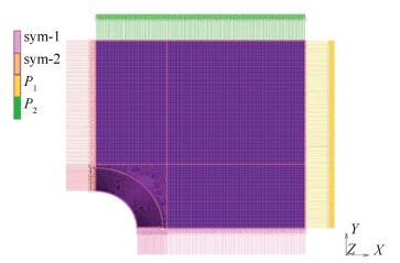
For discussion, the stress states under different load ratios for this problem are first clarified. The problem is analyzed in this paper employing elastic-plastic finite element analysis and the same basic conditions as used in Ref. [9]. In this case, the diameter of the hole D and the length of the plate L are 20 and 100 mm, respectively. The material of the plate adopts an elastic-perfectly plastic material model and follows the von Mises criterion. The elastic modulus is 207 GPa, Poisson's ratio is 0.3 and the yield stress is 300 MPa. All finite element analyses are carried out in MSC Marc with plane stress four-noded quad elements. The finite element meshes and boundary conditions are shown in Fig. 10. A quarter model is used owing to the symmetry of the geometry and loading. Approximately 17 000 elements are meshed.
|
Figure 10 Finite element model of the square plate with a central hole |
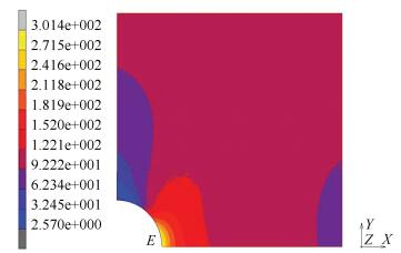
For the convenience of illustration, we take the example of P1/P2=0.25, P1=25 MPa, and P2=100 MPa for λ=P1/P2∈[0, 1]. The equivalent Mises stress contours under the combined loading with constant load P1 and peak cyclic load P2 are shown in Fig. 11. It is seen that the maximum stress is located at point E. The shakedown of the square plate thus depends on the shakedown behavior of the critical point E. Figs. 12(a) and 12(b) show the stress components along the directions of the constant load P1 and cyclic load P2, respectively. In this situation, the component of the stress along the direction of constant load P1 at point E is 5.2 MPa. The component of the stress along the direction of the cyclic load P2 at point E is 305.2 MPa, which is much larger than 5.2 MPa. Therefore, the stress under the combined load (P1+P2max) is almost exactly along the direction of the cyclic load P2. Because the direction of the reference elastic stress generated at point E by the cyclic load P2 is the same as the direction of the cyclic load P2. The angle θ between the stress generated by the combined loading with the constant load and the peak cyclic load and the reference elastic stress generated by the cyclic load is thus almost zero.
|
Figure 11 Equivalent stress of the plate for λ=P1/P2=0.25 |

|
Figure 12 Component stresses with the same direction as the constant load and the cyclic load |
According to Eq. (31), the peak of the shakedown limit load P2maxS is equal to twice the elastic limit load of the structure subjected to only the cyclic load P2e; i.e., P2maxS=2P2e.Fig. 9 shows that the shakedown limit load of the cyclic load is twice the elastic limit load of only the cyclic load within allowable error. The results in Ref. [9] are therefore consistent with the analytical results of the present paper.
5 ConclusionsAccording to Polizzotto's extended static shakedown theorem for combined loading with a constant load and cyclic load, the shakedown condition of a structure was derived. A general expression for the shakedown limit load was then derived through the analytic analysis of the shakedown condition. The general effect of the combined loading on the structural shakedown limit load was proposed. The following conclusions are drawn from the results of the study.
(1) For combined loading, shakedown is affected by the scope of the cyclic load and the angle θ between the stress of the combined loading with the constant load and the peak of the cyclic load and the reference elastic stress of the cyclic load. The constant load affects the structural shakedown behavior through the angle θ.
(2) If the angle θ is zero, the scope of the shakedown limit load is equal to twice the elastic limit load of only the cyclic load.
(3) If θ∈(0°, 90°), the scope of the cyclic load is not larger than twice the product of the elastic limit load of only the cyclic load and the cosine of θ for the structure to shake down. The scope of the shakedown limit load is less than twice the elastic limit load of only the cyclic load.
(4) If the angle θ is greater than or equal to 90°, the structure cannot reach shakedown under the combined loading. The structural safety load should be evaluated using the plastic limit load.
(5) The analytical solutions are applied to two examples, which are the hollow tension specimen subjected to constant tension and cyclic torsion, and the square plate with a central hole subjected to constant and cyclic tension. The obtained results are consistent with the ones in the literature.
| [1] |
Melan E. The Mises-Hencky's stress distribution of continuum under variable load.
Conference Report of the Vienna Academy of Science, Mathematic Natural Scientific Division, Section IIa, 1938, 147: 73-87.
( 0) 0)
|
| [2] |
Koiter W T. General theorems for elastoplastic solids.
Amsterdam, 1960: 167-221.
( 0) 0)
|
| [3] |
Polizzotto C. On the conditions to prevent plastic shakedown of structures: Part Ⅰ-Theory and Part Ⅱ-The plastic shakedown limit load.
Journal of Applied Mechanics, 1993, 60(1): 15-25.
DOI:10.1115/1.2900750 ( 0) 0)
|
| [4] |
Oh Chang-Sik, Kim Yun-Jae, Park Chi-Yong. Shakedown limit loads for elbows under internal pressure and cyclic in-plane bending.
International Journal of Pressure Vessels and Piping, 2008, 85(6): 394-405.
DOI:10.1016/j.ijpvp.2007.11.009 ( 0) 0)
|
| [5] |
Li Tianbai, Chen Haofeng, Chen Weihang, et al. On the shakedown analysis of welded pipes.
International Journal of Pressure Vessels and Piping, 2011, 88(8/9): 301-310.
DOI:10.1016/j.ijpvp.2011.06.005 ( 0) 0)
|
| [6] |
Chen Shenshen, Liu Yinghua, Li Jun, et al. Performance of the MLPG method for static shakedown analysis for bounded kinematic hardening structures.
European Journal of Mechanics A/Solids, 2011, 30(2): 183-194.
DOI:10.1016/j.euromechsol.2010.10.005 ( 0) 0)
|
| [7] |
Simon J W. Direct evaluation of the limit states of engineering structures exhibiting limited, nonlinear kinematical hardening.
International Journal of Plasticity, 2013, 42: 141-167.
DOI:10.1016/j.ijplas.2012.10.008 ( 0) 0)
|
| [8] |
Heitzer M, Staat M, Reiners H, et al. Shakedown and ratchetting under tension-torsion loadings: analysis and experiments.
Nuclear Engineering and Design, 2003, 225(1): 11-26.
DOI:10.1016/S0029-5493(03)00134-1 ( 0) 0)
|
| [9] |
Muscat M, Hamilton R, Boyle J T. Shakedown analysis for complex loading using superposition.
The Journal of Strain Analysis for Engineering Design, 2002, 37(5): 399-412.
DOI:10.1243/030932402760203865 ( 0) 0)
|
| [10] |
Abdalla H F, Megahed W M, Younan M Y A. A simplified technique for shakedown limit load determination.
Nuclear Engineering and Design, 2007, 237(12/13): 1231-1240.
DOI:10.1016/j.nucengdes.2006.09.033 ( 0) 0)
|
| [11] |
Abdalla H F, Megahed M M, Younan M Y A. A simplified technique for shakedown limit load determination of a large square plate with a small central hole under cyclic biaxial loading.
Nuclear Engineering and Design, 2011, 241(3): 657-665.
DOI:10.1016/j.nucengdes.2010.11.019 ( 0) 0)
|
| [12] |
Vermaak N, Valdevit L, Anthony E, et al. Implementations of shakedown for design of actively cooled thermos structural panels.
Journal of Mechanics of Materials and Structures, 2011, 6(6): 1313-1327.
( 0) 0)
|
| [13] |
Seshadri R. Inelastic evaluation of mechanical and structural components using the generalized local stress strain method of analysis.
Nuclear Engineering and Design, 1995, 153(2/3): 287-303.
DOI:10.1016/0029-5493(95)90020-9 ( 0) 0)
|
| [14] |
Mackenzie D, Boyle J T, Hamilton R. The elastic compensation method for limit and shakedown analysis: a review.
The Journal of Strain Analysis for Engineering Design, 2000, 35(3): 171-188.
DOI:10.1243/0309324001514332 ( 0) 0)
|
| [15] |
Chen Haofeng, Ponter A R S. Structural integrity assessment of superheater outlet penetration tube plate.
International Journal of Pressure Vessels and Piping, 2009, 86(7): 412-419.
DOI:10.1016/j.ijpvp.2009.01.008 ( 0) 0)
|
| [16] |
Ure J, Chen Haofeng, Tipping D. Integrated structural analysis tool using the linear matching method part 1-Software development.
International Journal of Pressure Vessels and Piping, 2014(120/121): 141-151.
DOI:10.1016/j.ijpvp.2014.05.004 ( 0) 0)
|
| [17] |
Spiliopoulos K V, Panagiotou K D. A residual stress decomposition based method for the shakedown analysis of structures.
Computer Methods in Applied Mechanics and Engineering, 2014, 276(1): 410-430.
DOI:10.1016/j.cma.2014.03.019 ( 0) 0)
|
| [18] |
Spiliopoulos K V, Panagiotou K D. A numerical procedure for the shakedown analysis of structures under cyclic thermomechanical loading.
Archive of Applied Mechanics, 2015, 85(9): 1499-1511.
DOI:10.1007/s00419-014-0947-6 ( 0) 0)
|
| [19] |
Chen Haofeng, Ure J, Li Tianbai, et al. Shakedown and limit analysis of 90° pipe bends under internal pressure, cyclic in-plane bending and cyclic thermal loading.
International Journal of Pressure Vessels and Piping, 2011, 88(5/6/7): 213-222.
( 0) 0)
|
| [20] |
Abdalla H F. Shakedown boundary determination of a 90° back-to-back pipe bend subjected to steady internal pressures and cyclic in-plane bending moments.
International Journal of Pressure Vessels and Piping, 2014, 116: 1-9.
DOI:10.1016/j.ijpvp.2014.01.001 ( 0) 0)
|
| [21] |
Nayebi A, Tirmomenin A, Damadam M. Elasto-Plastic Analysis of a functionally graded rotating disk under cyclic thermo-mechanical loadings considering continuum damage mechanics.
International Journal of Applied Mechanics, 2015, 7(2): 1550026, 1-16.
DOI:10.1142/S175882511550026X ( 0) 0)
|
 2017, Vol. 24


