A blade is a typical complex component that is widely used in the turbine machinery [1]. The roughness and precision of the blade surface has important effect on the turbine's performance, efficiency and service life, which therefore requires a high standard requirement for the machining and measurement of blade [2]. The measurement of turbine blade profile is very crucial, with which it can offer a critical evaluation of the machining quality and to give reasonable instructions for the following evaluation of blades.
The shape of the blade is complex, and it is a difficult task to measure a turbine blade. As advanced measuring equipment appeared in the 1960s, coordinate measuring machines (CMMs) became one of the key devices in reverse engineering and plays an important role in product accuracy testing [3]. CMMs is now widely used in the accuracy measurement of complicated manufactured products, such as turbine blades, gears, axis, rods and other irregular shape's measurement. A 5-axis CMMs (a dividing head with two rotational axes) can perform the complicated measurement of blades [4]. The measurement accuracy of CMMs increased rapidly and even approaches to the micrometer scales. It can even reach sub-micron order accuracy when the high precision measuring probe is used. Savio used 5-axis CMMs to measure the turbine blade, whose uncertainty is 5-10 μm [5]. Now, 5-axis CMMs are the most widely used and reliable measuring equipment of blades. Even so, the measurement efficiency of CMM is low because the measuring sampling strategy is still performed using the point-by-point method [6]. Furthermore, the cost of 5-axis CMMs is very high, and it is generally used in laboratory testing because it requires high-standard measuring environment. Now, a lot of research has been carried out concerning the measurement path planning to improve the measuring efficiency and decrease the work burden [7-9]. Among these measurements, planning of 5-axis CMMs, can be classified into two kinds. One is the parallel mode, of which the measuring probe is set to be collinear to the surface normal at the measuring point [10]. The other is the rotation mode, of which the measuring probe is normal to the tangent line but not colinear to normal at the measuring point[11]. Furthermore, existing works mainly discuss the feasibility of measurement planning on the measurement of blade by CMMs [12]. Now, there has been a lot of research on the measuring uncertainty estimation of CMMS [13-15], but few focus on the uncertainty and efficiency comparison of these methods on the measurement of blades by 5-axis CMMs. Thus, it is necessary to explore the individual characteristics of these two kinds of measurement planning in measuring the blade via 5-axis CMMs.
In this paper, the theoretical backgrounds of both the parallel and rotation modes of 5-axis CMMs are analyzed first. Then the measurement experiments of the blade in these two modes are performed. Finally, the individual measurement uncertainties of the blade by 5-axis CMMS of the two modes are examined.
2 Theoretical BackgroundThe blade in turbine machinery is always a typical twisted freeform surface, of which the characteristics of each cross section of twisted blade are different from each other's at different heights. The curvature of the blade surface varies at each different sampling point, which means it is necessary to program the sampling strategy to perform the measurement operation of blade surface.
The size and profile of blade surface is always measured by 5-axis CMMs. The common measuring practice is to divide the blade into several parts in the length direction, and then the divided profiles are discretized into dozens of sampling points. The blade is measured with the measuring head along the cross-section edges one by one. Finally, the curved edge is fitted based on the measured points and then the whole surface.
The measurement sampling strategy of blade can be generally classified into two kinds. One is the parallel mode, whose measuring probe is set to be collinear to the surface normal at the measuring point. The other is the rotation mode, which is defined as the measuring probe being normal to the tangent line at the measuring point and not collinear to the surface's normal [11].
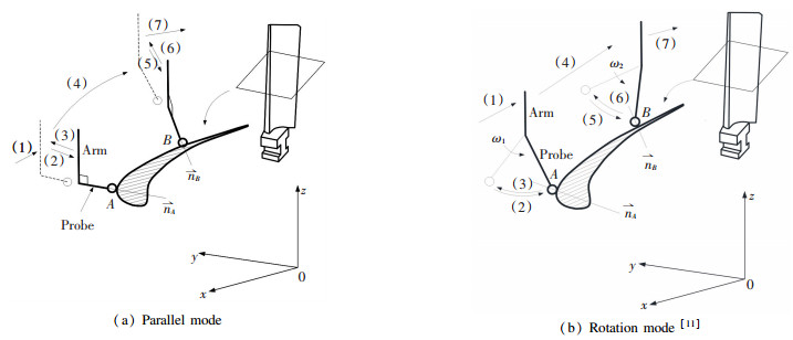
The parallel mode of measuring strategy can be illustrated as shown in Fig. 1(a). The measuring probe always keeping normal to the measuring arm and collinear to the surface's normal at the measuring point. Based on the programmed sampling strategy, the measuring path is planned and generated, and the measuring process is describes below:
|
Fig.1 Sampling/measuring strategy of the freeform surface |
(1) First, move the measuring arm to the defined position/posture.
(2) Second, rotate the end measuring arm and set the measuring probe normal to the surface and point to the measuring point A, then move forward the end measuring arm and probe approaching to the measuring point A along the normal line till the measuring head contacts the measuring point to perform the measuring operation.
(3) Third, retreat the measuring arm and probe back to the defined position.
(4) Fourth, move the measuring arm along the defined path to the next position.
(5) Fifth, rotate the measuring arm and let the posture of the measuring probe point normal to the surface at the measuring point B, then move the measuring arm and make the probe directly contact measuring point B and perform the measuring operation.
(6) Sixth, retreat the end arm and probe back to the original position again.
(7) Seventh, repeat the operation mentioned above till all the measurements are done.
As for the rotation mode, the posture of measuring arm/head is still normal to the cross section at the measuring point, but not normal to surface at the measuring points. The measuring strategy is illustrated in Fig. 1 (b) [11]:
(1) First, move the measuring arm and probe to a defined position.
(2) Second, rotate the measuring arm and probe perpendicular to the cross section profile at the measuring point, then rotate the measuring arm and head to contact the measuring point A and conduct the measuring operation.
(3) Third, return the measuring probe and head back to the original position and correct its posture.
(4) Fourth, move the arm and head to the next position.
(5) Fifth, rotate the measuring arm and probe perpendicular to the cross section profile at the measuring point, and then rotate the measuring arm till the measuring head contacting with the sampling point B and perform the measuring operation.
(6) Sixth, return the measuring arm and probe back to the original position/gesture.
(7) Seventh, repeat the above manipulation and move to the next position till the end.
Closely examining these two measuring modes, it is obviously the sampling strategy of rotation mode is more flexible than that of the parallel one. The measuring probe of the rotation mode needn't to be normal to blade surface at measuring points all the time, which permits much larger movement space for the measuring arm and probe. It can also offer much convenience for the measuring arm and probe to avoid the potential collision between the workpiece and moving machine body because of the narrow gaps.
The CMMs' measurement accuracy of a complicated surface is effected by many factors. It is hard to accurately quantize the influence factors with a mathematical expression, and therefore the error sources can not be dealt with in a defined ideal means, which result the CMMS' unavoidable measurement uncertainty. Both the parallel and rotation measuring mode of 5-axis CMMs have different measuring and sampling method and strategy, which means that they may have different measurement uncertainty and efficiency. Thus it is necessary to examine the measurement uncertainty of these measuring and sampling methods to give a critical evaluation and instruction for the precision measuring of blade by 5-axis CMMs.
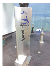
3 Measurement Experiment and Evaluation 3.1 Measuring ExperimentA general twisted blade with unknown parameters shown in Fig. 2 is used in the measurement experiment to discuss the measurement uncertainty. The measurement experiment is conducted on a 5-axis CMMs. The parameters of the CMMs are shown in Table 1.
|
Fig.2 The blade for measurement experiment |
| Table 1 Parameters of Zeiss CMMs |
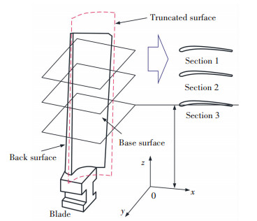
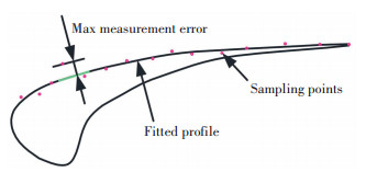
To evaluate the measurement accuracy of CMMs on different blade surfaces with different characteristics, the measurement actions were performed on both the back and base surfaces of the blade. The blade is first divided into two parts, which are back surface and base surface. Then three groups of truncated profiles were generated from the top to the bottom of blade by dividing the blade surface into several parts along vertically, as shown in Fig. 3. Here, the height of the blade surface is 20 mm, and each profile was taken at each 5 mm from the top of the blade to the bottom. Sampling points were generated by discretizing and choosing the points every equal distance along the curved edge of the truncated surface profile. Therefore, the planning path of both modes were generated base on their principle by generating a sampling program with the CMMs' built-in software. The sampled datum are handled and then fitted with a quantic polynomial into a series of parallel profiles. The measurement errors were calculated by evaluating the deviation between the fitted polynomial curve and the measurement value at the sampling points as illustrated in Fig. 4. The measurement uncertainty was examined and discussed based on the maximum of the deviation of each truncated profiles.
|
Fig.3 The discretized pattern of blade |
|
Fig.4 The measurement error evaluation method |
A measurement example is performed to verify both the sampling strategies' feasibility in measuring the blade surface. Fig. 5 shows one group of the samples points and the fitted section profiles of all the truncated cross-section on both the back and base surface. It shows that both the profile's shapes fitted from both parallel and rotation modes all can exactly describe the curvature variation trend of the blade surface. Therefore, it can conclude that both sampling methods can be adopted in sampling the blade surface's information in CMMs.
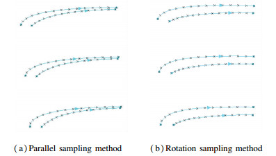
|
Fig.5 One group of the fitted cross-section profiles of both sampling methods |
3.2 Results and Discussion
To evaluate the measurement uncertainty of both of the sampling methods, the measurement and sampling operations were repeated six times and the sampling datum were examined comprehensively. Fig. 6 illustrates the errors of each profiles on both the back and base surfaced of the blade.
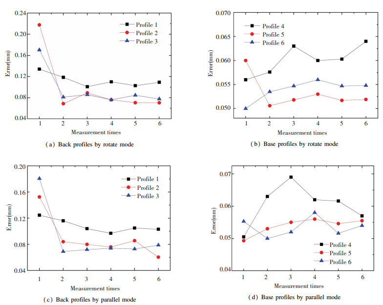
|
Fig.6 Measurement errors of each profiles |
From these figures shown above, it can be seen that the measurement errors varied with each other a certain extent both for the parallel and rotation modes, which means that the measurement uncertainty of CMMs on blade surface can not be neglected. It is also shown that the measurement uncertainty of the truncated cross-section profiles decreases from the top surface to the bottom surface of the blade. This trend can be seen in Fig. 7, of which shows the average measurement errors of the six times measurement of each profiles. The reason may be that the length of the profile curve on the top blade is much longer than that on the bottom blade, which enlarges the uncertainty of the measuring path and length. Other reasons may be that the curvature of the profiles on the bottom blade varies much more even than that on the top blade, which weakens the uncertainty of the surface complicity and sampling strategy.
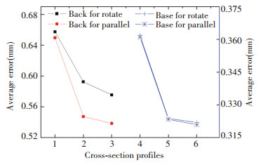
|
Fig.7 Average measurement errors of each profiles |
Another important point can be revealed from Fig. 7 which is that in the average measurement errors there also appears an interesting phenomena. The average measurement error by rotation mode is slightly larger than that of the parallel mode, which means that the measurement uncertainty by rotation mode is more serious than that of parallel sampling mode. Furthermore, the average measurement errors of cross-section profiles on the back surface between two sampling modes are much larger than these on the base surface. This means that the parallel sampling method is superior to the rotation mode. However, the differences of the blade profiles between two sampling modes are within a small extent though they differs from each other, which means that both two sampling modes can be used in measuring the blade surface by CMMS in some conditions. Notably, the rotation sampling method may become the first choice when operation space is limited.
4 ConclusionsThe measurement uncertainty of blade surface by CMMs was investigated based on two sampling modes, of which one is the parallel mode and the other is the rotation mode. The measurement operations of blade surface were performed on a 5-axis Zeiss CMMs. It found that the measurement of blade surface by CMMs shows much uncertainty for both of two sampling modes because of the complexity of the blade surface. The back surface's measurement uncertainty is a little larger than the base surface's. Moreover, the measurement uncertainty also exhibits the same trend, being the measurement uncertainty of cross-section profiles on the top blade surface is larger than that of the bottom blade surface. In addition, the difference between the measurement uncertainties of two sampling methods is small, especially for the base blade surface. The research shows that both sampling modes, the parallel mode and the rotation mode can also be used in measuring the complicated blade surface by CMMs when the accuracy standard is not too high.
Furthermore, the rotation mode may become the first choice when the operation space is limited.
| [1] |
Graening L, Menzel S, Hasenjäger M, et al. Knowledge extraction from aerodynamic design data and its application to 3D turbine blade geometries. Journal of Mathematical Modelling and Algorithms, 2008, 7(4): 329-350. DOI:10.1007/s10852-008-9094-9 (  0) 0) |
| [2] |
Huang Junhui, Wang Zhao, Gao Jianmin, et al. Overview on the profile measurement of turbine blade and its development. Proceedings of 5th International Symposium on Advanced Optical Manufacturing and Testing Technologies. Washington: SPIE, 2010. 76560L-1-76560L-11.
(  0) 0) |
| [3] |
Song C K, Kim S W. Reverse engineering: Autonomous digitization of free-formed surfaces on a CNC coordinate measuring machine. International Journal of Machine Tools and Manufacture, 1997, 37(7): 1041-1051. DOI:10.1016/S0890-6955(96)00059-4 (  0) 0) |
| [4] |
Chang Hui-Chin, Lin Alan C. Automatic inspection of turbine blades using a 3-axis CMM together with a 2-axis dividing head. The International Journal of Advanced Manufacturing Technology, 2005, 26(7/8): 789-796. DOI:10.1007/s00170-003-1877-6 (  0) 0) |
| [5] |
Savio E, De Chiffre L. An artefact for traceable freeform measurements on coordinate measuring machines. Precision Engineering, 2002, 26(1): 58-68. DOI:10.1016/S0141-6359(01)00098-8 (  0) 0) |
| [6] |
Kawalec A, Magdziak M. The selection of radius correction method in the case of coordinate measurements a turbine blade. Proceedings of 11th International Symposium on Measurement and Quality Control 2013. Cracow-Kielce, 2013. https://pdfs.semanticscholar.org/1945/86b682f5e15363c4676f9bffe5b98161bee6.pdf.
(  0) 0) |
| [7] |
de Aquino Silvaa J B, Burdekin M. A modular space frame for assessing the performance of co-ordinate measuring machines (CMMs). Precision Engineering, 2002, 26(1): 37-48. DOI:10.1016/S0141-6359(01)00096-4 (  0) 0) |
| [8] |
Jakubiec W, Plowucha W, Starczak M. Analytical estimation of coordinate measurement uncertainty. Measurement, 2012, 45(10): 2299-2308. DOI:10.1016/j.measurement.2011.09.027 (  0) 0) |
| [9] |
Choi W, Kurfess T R, Cagan J. Sampling uncertainty in coordinate measurement data analysis. Precision Engineering, 1998, 22(3): 153-163. DOI:10.1016/S0141-6359(98)00011-7 (  0) 0) |
| [10] |
Cheung ChiFai, Ren MingJun, Kong LingBao, et al. Modelling and analysis of uncertainty in the form characterization of ultra-precision freeform surfaces on coordinate measuring machines. CIRP Annals-Manufacturing Technology, 2014, 63(1): 481-484. DOI:10.1016/j.cirp.2014.03.032 (  0) 0) |
| [11] |
Li Y Z, Zhang G H, Liu Z S, et al. Research on the measurement uncertainty of blade surface measured by coordinates measuring machines. Industrial Engineering & Management, 2015, 4: 174. DOI:10.4172/2169-0316.1000174 (  0) 0) |
| [12] |
Edgeworth R, Wilhelm R G. Adaptive sampling for coordinate metrology. Precision Engineering, 1999, 23(3): 144-154. DOI:10.1016/S0141-6359(99)00004-5 (  0) 0) |
| [13] |
Aggogeri F, Barbato G, Barini E M, et al. Measurement uncertainty assessment of Coordinate Measuring Machines by simulation and planned experimentation. CIRP Journal of Manufacturing Science and Technology, 2011, 4(1): 51-56. DOI:10.1016/j.cirpj.2011.01.007 (  0) 0) |
| [14] |
Phillips S D, Borchardt B, Estler W T, et al. The estimation of measurement uncertainty of small circular features measured by coordinate measuring machines. Precision Engineering, 1998, 22(2): 87-97. DOI:10.1016/S0141-6359(98)00006-3 (  0) 0) |
| [15] |
Hansen H N, De Chiffre L. An industrial comparison of coordinate measuring machines in Scandinavia with focus on uncertainty statements. Precision Engineering, 1999, 23(3): 185-195. DOI:10.1016/S0141-6359(99)00009-4 (  0) 0) |
 2019, Vol. 26


