2. School of Naval Architecture and Ocean Engineering, Harbin Institute of Technology (Weihai), Weihai 264209, Shandong, China;
3. School of Mechatronic Engineering, Jiangsu Normal University, Xuzhou 221116, Jiangsu, China
The hydraulic transmission has the characteristics of flexible layout, high power density ratio, and convenient control, which is widely used in mechanical equipment. In the hydraulic transmission system, it is often necessary to control the force or torque of the actuator, which can be achieved by adjusting the pressure of the hydraulic system. In order to achieve pressure regulation in the hydraulic transmission system, pressure reducing valve and booster cylinder are commonly used. The pressure reducing valve uses the throttling pressure loss at the valve port to achieve pressure reduction regulation, but it cannot achieve pressurization, and the throttling energy loss is large. The pressure regulating mode of booster cylinder can realize pressure rise and pressure reduction without throttling loss, but the stroke of hydraulic cylinder is limited and the flow provided is limited, so it is necessary to study the hydraulic transformer which can supply oil continuously.
The earliest form of hydraulic transformer that can supply oil continuously is series connection of hydraulic pump or hydraulic motor. It is to connect the rotating shafts of hydraulic pump or hydraulic motor that can rotate continuously together through coupling. The pressure ratio is equal to the displacement ratio of both. One or both of them are variable elements, which can realize the adjustment of displacement, and the pressure ratio can be realized by adjusting displacement. However, the direct series hydraulic transformer is huge in volume, heavy in weight, low in transmission efficiency, and slow in dynamic response, which seriously limits its application. In order to improve the integration degree of this kind of hydraulic transformer, INNAS company has put forward an integrated hydraulic transformer (IHT)[1], Achten et al.[1] have studied the structural design of the IHT, the application principle of the hydraulic transformer in the constant voltage network, and the application in the hybrid electric vehicle[2-4].
Because of its compact structure and high efficiency, IHT has become a research hotspot. Ouyang et al.[5-6] studied the manual IHT, designed and manufactured an IHT principle prototype, which is based on the design of the inclined shaft plunger hydraulic motor. Ma et al.[7] studied the design principle, flow field simulation, and experimental test of the IHT, and analyzed the noise and flow pulsation characteristics of IHT. Liu et al.[8] studied the application of hydraulic transformer in TBM cutterhead hybrid drive system. The secondary regulation system based on three port IHT cooperates with frequency conversion motor to form cutterhead hybrid drive system, which can improve the efficiency of cutterhead drive system by about 5% under typical working conditions. Kwan et al.[9-11] studied the hydraulic cylinder driven by hydraulic transformer and its application in hybrid excavator. Lu et al.[12-13] has developed a hydraulic transformer with electro-hydraulic servo control, which can realize the transformer's pressure ratio of 0-2. Shi et al.[14] studied the hydraulic system of current generation based on the hydraulic transformer. The three port IHT was used to control the impeller speed and the generator speed, improve the energy capture efficiency and output stability of current generation group. Jiang et al.[15-16] studied the development process, flow characteristics, and pressure characteristics of the three port IHT, developed the IHT controlled by swing hydraulic motor, built a test-bed, and carried out the test of the pressure ratio and the research of the control strategy. Yang et al.[17-18] studied the flow characteristics and torque characteristics of the dual variable IHT, and studied the characteristics of the three port IHT when the displacement is a variable parameter. Liu et al.[19] studied the PID control strategy of the distribution plate of the hydraulic transformer. Wu and Jing et al.[20-23] studied the control of IHT on hydraulic motor. According to the working principle and dynamic equation of the motor control system of the hydraulic transformer, using the linearization theory, the transfer function of the system was established and simplified, and the theoretical analysis and simulation analysis were carried out. Their research shows that the motor control system of the hydraulic transformer is not suitable for the high-precision torque and speed control system. An adaptive reversing drive system based on the hydraulic transformer is proposed, which is controlled by the hydraulic single. The directional valve realizes the control of the hydraulic motor, the adaptive switching of the wheel drive/brake of the hydraulic motor, and the switching of the working mode. Ning et al.[24-25] studied the application of three port IHT in the hydraulic luffing system of armored rescue vehicle, used the hydraulic transformer to control the hydraulic cylinder, and simulated the control strategy. Shen et al.[26-29] has carried out the research on the control of hydraulic cylinder by three port IHT and its simulation control of the boom working condition of excavator, and studied different control strategies, which can improve the control performance of hydraulic cylinder. Gaspar et al.[30] put forward the scheme of wave energy recovery by using hydraulic transformer. It is pointed out that the adoption of hydraulic transformer is beneficial to the power take-off system.
At present, the IHT processes three ports on the distribution plate. In this paper, the expansion characteristics of port number of the distribution plate of the IHT were analyzed and compared, and the transformation characteristics of the IHT with more than three ports were analyzed, which provides theoretical basis and reference for the design and application of the IHT.
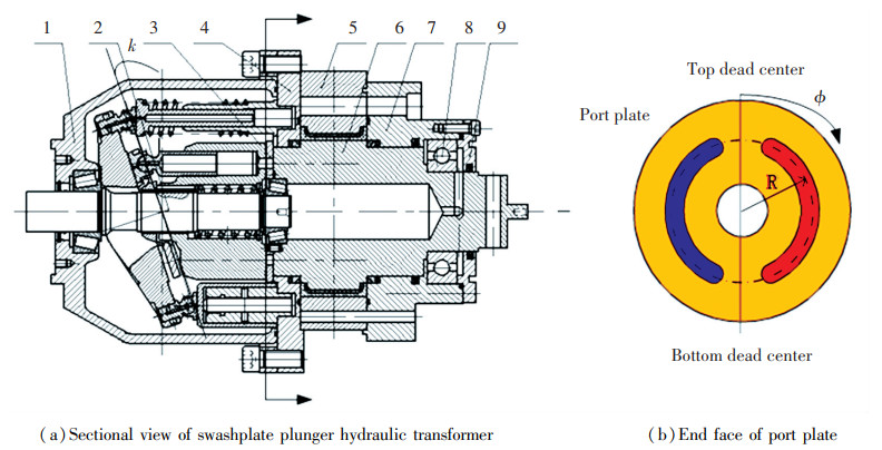
1 Working Principle of Axial Plunger Type Hydraulic TransformerThe axial piston type hydraulic components have the characteristics of high power density ratio, high pressure, and are easy to manufacture, so they are widely used in the field of hydraulic transmission. The IHT is a new design based on the basic structure of the axial piston hydraulic components. The structural principle of the axial plunger type element is shown in Fig. 1. When the cylinder block of the axial plunger hydraulic component rotates, the plunger moves back and forth in the cylinder block, resulting in the volume change of the closed cavity. The volume change is connected with the corresponding port of the port plate to realize the function of oil suction or oil discharge.
|
1-IHT's case; 2-IHT's axis; 3-IHT's plate; 4-Intermediate connector; 5-Motor stator; 6-Motor rotor; 7-Right end cap; 8-Bearing; 9-Bearing end cover Fig.1 Structural schematic diagram of axial plunger hydraulic transformer |
The tilt angle between the cylinder block and the tilt element of the axial piston type hydraulic elementis k. When the tilt element makes the cylinder block rotate, it will drive the plunger to produce expansion movement relative to the cylinder block. The displacement equation of the plunger relative to the cylinder block is as follows:
| $ s = R(1 - \cos \varphi )\tan k $ | (1) |
where s represents expansion displacement of plunger relative to cylinder block, R represents distribution circle radius of plunger; φ is rotation angle of cylinder block relative to top and bottom dead center; k is angle between inclined parts and cylinder block.
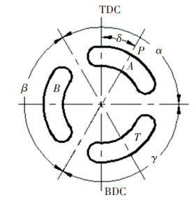
2 Research on Pressure Ratio Characteristics of Three Ports IHTThree distribution slots are machined on the distribution plate of the three ports IHT, which are disconnected from each other and are three independent distribution ports. In the CPR network or hydraulic system, one port is connected to the high-pressure pipeline, one port is connected to the load, and one port is connected to the fuel tank. The end face of distribution plate of three ports IHT is shown in Fig. 2.
|
Fig.2 End diagram of distribution plate of three-port IHT |
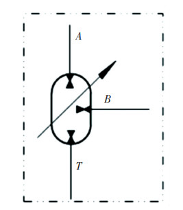
The functional symbols of the three port IHT are shown in Fig. 3.
|
Fig.3 Functional symbols of 3-ports IHT |
The control angle of the integrated three port plunger type hydraulic transformer is defined as δ, and the action angle intervals of the three ports are obtained.
Envelope angle of port A:
[0.5α+δ, δ+γ+β+0.5α]
Envelope angle of port B:
[δ+γ+β+0.5α, δ+γ+0.5α]
Envelope angle of port T:
[δ+γ+0.5α, 0.5α+δ]
where α represents envelope angle of port A; β is envelope angle of port B; γ is envelope angle of port T.
As shown in Fig. 2, when the cylinder body rotates, each plunger is successively connected with three port openings. The function angle range of each port is brought into the displacement formula 1 of the axial piston type hydraulic component. The displacement of the plunger multiplied by the area of the plunger can get the geometric displacement of each port as follows:
| $ \left\{ {\begin{array}{*{20}{c}} {{V_B} = \frac{\pi }{4}{d^2}zR\tan k\left( {\cos \left( {\delta + \gamma + \frac{\alpha }{2}} \right) - } \right.\left. {\cos \left( {\delta + \gamma + \beta + \frac{\alpha }{2}} \right)} \right)}\\ {{V_A} = \frac{\pi }{4}{d^2}zR\tan k\left( {\cos \left( {\delta + \gamma + \beta + \frac{\alpha }{2}} \right) - } \right.\left. {\cos \left( {\delta + \frac{\alpha }{2}} \right)} \right)}\\ {{V_T} = \frac{\pi }{4}{d^2}zR\tan k\left( {\cos \left( {\delta + \frac{\alpha }{2}} \right) - \cos (\delta + } \right.\left. {\left. {\gamma + \frac{\alpha }{2}} \right)} \right)} \end{array}} \right. $ | (2) |
where d is plunger diameter; z is plunger number.
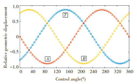
The numerical solution curve of the geometric displacement of each port is shown in Fig. 4. The positive value of the relative geometric displacement represents that when the cylinder rotates in the direction shown in Fig. 2, the plunger discharges oil to the corresponding port, and the negative value of the relative displacement represents that when the cylinder rotates in the direction shown in Fig. 2, the oil is drawn from the corresponding port. It can be seen from Fig. 4 that when the control angle of the hydraulic transformer is zero, the displacement of port A is zero, because when the control angle is zero, the area of port A on both sides of the upper and lower dead point line is equal, the displacement of the plunger entering port A and leaving port A is equal, and the displacement difference is zero, so the opposite geometric displacement is zero. The maximum displacement is 86.6% of the base element.
|
Fig.4 Relative geometric displacement of each port of three port IHT |
From Fig. 4, it can be seen that when the control angle is zero, the displacement of port A is zero. From Fig. 2, it can be seen that when the control angle is zero, the connecting line of port A is symmetrical with respect to the upper and lower dead points, so the oil absorption and discharge of each plunger at port A are equal, and the sum is equal to zero. The total displacement of three ports of the three port IHT is always equal to zero, which satisfies the flow conservation theorem for the hydraulic transformer. If the mechanical energy loss of the hydraulic transformer is ignored, the transformation process satisfies the energy conservation, so it is more efficient than the throttling transformation. When the control angle changes in the range of 0° - 120°, the displacement of port T changes from suction to discharge.
In Fig. 4, the positive value of displacement represents oil discharge, which works under the working condition of hydraulic pump; the negative value of displacement represents oil suction and works under the working condition of hydraulic motor. According to the torque calculation formula of the axial piston hydraulic components, the displacement of each port is brought into the torque formula, and the average torque of each port of the IHT is obtained:
| $ {T_A} = \frac{{{p_A} \cdot {d^2}zR\tan k}}{8} \cdot \sin \frac{\alpha }{2} \cdot \sin \delta $ | (3) |
| $ {T_B} = \frac{{{p_B} \cdot {d^2}zR\tan k}}{8} \cdot \sin \frac{\beta }{2} \cdot \sin \left( {\delta - \frac{\alpha }{2} - \frac{\beta }{2}} \right) $ | (4) |
| $ {T_T} = \frac{{{p_T} \cdot {d^2}zR\tan k}}{8} \cdot \sin \frac{\gamma }{2} \cdot \sin \left( {\frac{\alpha }{2} + \frac{\gamma }{2} + \delta } \right) $ | (5) |
The torque produced by the three ports of the IHT acts on the rotating shaft of the hydraulic transformer. According to the torque balance formula produced by the three ports, the pressure ratio of the hydraulic transformer is obtained, which is the ratio of the output pressure to the input pressure. The expression of the pressure ratio of 3 ports IHT λ3 is as follows:
| $ {\lambda _3} = \frac{{{p_B}}}{{{p_A}}} = - \frac{{\sin \frac{\alpha }{2} \cdot \sin \delta + \frac{{{p_T}}}{{{p_A}}} \cdot \sin \frac{\gamma }{2} \cdot \sin \left( {\delta + \frac{\alpha }{2} + \frac{\gamma }{2}} \right)}}{{\sin \frac{\beta }{2} \cdot \sin \left( {\delta - \frac{\alpha }{2} - \frac{\beta }{2}} \right)}} $ | (6) |
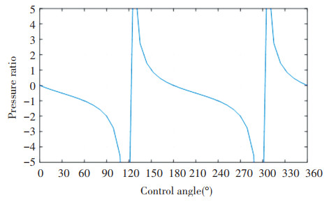
In actual operation, port T of the hydraulic transformer is connected to the oil tank, so the torque generated by port T can be ignored. Eq.(6) is solved to get the curve of pressure ratio of the three port IHT, as shown in Fig. 5.
|
Fig.5 Pressure ratio of three-port IHT |
It can be seen from Fig. 5 that when the rotation angle of the control angle of the three port IHT is 0°-120°, the pressure ratio increases with the increase of the rotation angle. The pressure ratio is zero at 0°, 1 at 60°, and infinite in theory at 120°. It can be explained in combination with Fig. 3 that when the control is 0°, the displacement of port A is zero, and the driving torque generated by port A is zero, and there is no driving force input. The pressure output of port B is zero, so the pressure ratio is zero, i.e., the output pressure of port B is zero; when the control angle is 60°, the connection between port A and port B is symmetrical with respect to the upper and lower dead points, i.e., the envelope angle of port A and port B is equal, and the displacement is equal, so the pressure ratio is - 1 in theory; when the control angle is close to 120°, the displacement of port B is close to zero, and that of port A is symmetrical. The torque drives the torque of port B close to zero, so in theory, the pressure ratio is the maximum value, i.e., the output pressure is high enough. But in practice, when the control angle is close to 120°, the displacement of port B is close to zero. Because there are problems of volume efficiency and leakage in the structure, the pressure will not continue to increase at this time, or even the pressure cannot be established.
It can be seen from Fig. 5 that with the rotation of the distribution plate of the hydraulic transformer, the change of the pressure ratio is periodic, with a period of 180°. Therefore, in the design of three port IHT, when the rotation angle of driving control angle is 180°, the change in a period can be realized. Therefore, when designing the rotation angle of the distribution plate of the hydraulic transformer, it only needs to rotate in one cycle to realize the full range change of the pressure ratio. When the control angle is within 0° - 120°, the pressure ratio is negative; when the control angle is within 120° - 180°, the pressure ratio is positive. The positive value of the pressure ratio represents that both port A and port B absorb or drain oil at the same time and input or output power at the same time, which does not meet the working requirements of the transformer. Therefore, the control angle of the three port IHT is not required to work within the range of 0° - 180°, and the control angle of the three port IHT is only required to work within the range of 0° - 120°.
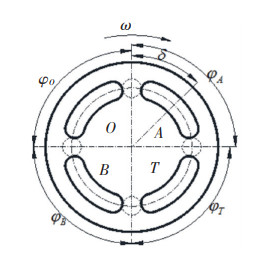
3 Research on Pressure Ratio Characteristics of 4-Ports IHTThe traditional plunger type hydraulic transformer is composed of a plunger type hydraulic pump and a plunger type hydraulic motor in direct series. Each component has two ports, so it is a 4-port hydraulic transformer. Referring to the structure of the three port IHT, the distribution board of the IHT can also be divided into four sections, i.e., the integrated four port hydraulic transformer is formed. The end face of the distribution plate of the four port IHT is shown in Fig. 6.
|
Fig.6 End diagram of valve plate of four-ports IHT |
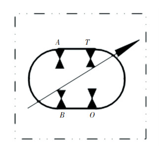
The function symbol of the four port IHT can be shown in Fig. 7. It can be seen that the function symbol of the four port IHT is similar to the function symbol of the hydraulic motor series hydraulic transformer of the hydraulic pump. The difference is that there is no coupling in the middle, and it shares a shell and a cylinder block.
|
Fig.7 Functional symbols of four-port IHT |
It is defined that the control angle of the integrated four port plunger type hydraulic transformer is zero when the center line of the distribution port coincides with the upper and lower dead center lines. The control angle at this time is shown in Fig. 6, and the action angle range of each distribution port is as follows:
Angle range of port A:
[-0.5φA+δ, δ+0.5φA]
Angle range of port T:
[δ+0.5φA, δ+0.5φA+φT]
Angle range of port B:
[δ+0.5φA+φT, δ+0.5φA+φT+φB]
Angle range of port O:
[δ+0.5φA+φT+φB, δ+0.5φA+φT+φB+φO]
where φA is envelope angle of port A; φB is envelope angle of port B; φT is envelope angle of port T; φO is envelope angle of port O.
The starting and stopping angles of each port are brought into the displacement formula 1 of the axial piston type hydraulic components. The displacement of the plunger multiplied by the area of the plunger gives the formula of the geometric displacement of each port:
| $ \left\{ {\begin{array}{*{20}{l}} {{V_A} = \pi {d^2}zR\tan k\left( {\cos \left( {\delta + 0.5{\varphi _A}} \right) - } \right.}\\ {\left. {\;\;\;{\kern 1pt} \cos \left( {\delta - 0.5{\varphi _A}} \right)} \right)/4}\\ {{V_T} = \pi {d^2}zR\tan k\left( {\cos \left( {\delta + 0.5{\varphi _A} + {\varphi _T}} \right) - } \right.}\\ {\left. {\;\;\;{\kern 1pt} \cos \left( {\delta + 0.5{\varphi _A}} \right)} \right)/4}\\ {{V_B} = \pi {d^2}zR\tan k\left( { c o s \left( {\delta + 0.5{\varphi _A} + {\varphi _T} + } \right.} \right.}\\ {\left. {\left. {\;\;\;{\varphi _B}} \right) - \cos \left( {\delta + 0.5{\varphi _A} + {\varphi _T}} \right)} \right)/4}\\ {{V_o} = \pi {d^2}zR\tan k\left( { c o s \left( {\delta + 0.5{\varphi _A} + {\varphi _T} + {\varphi _B} + } \right.} \right.}\\ {\left. {\left. {\;\;\;{\varphi _0}} \right) - \cos \left( {\delta + 0.5{\varphi _A} + {\varphi _T} + {\varphi _B}} \right)} \right)/4} \end{array}} \right. $ | (7) |
The numerical solution of the displacement of each port shows the curve as shown in Fig. 8. The positive value of the relative displacement represents that the plunger discharges oil to the corresponding port, and the negative value of the relative displacement represents that the plunger absorbs oil from the corresponding port. When the control angle of the hydraulic transformer is zero, the displacement of port A and port B is zero. It can be seen from Fig. 7 that when the control angle is zero, the area of port A on both sides of the upper and lower dead point connecting line is equal, and the displacement of the plunger entering port A and leaving port A is equal. The displacement is zero, so the relative geometric displacement is zero. The maximum displacement is 70.7% of the displacement of the base element.

|
Fig.8 Relative geometric displacement of each port of four-port IHT |
At the same time, the equal flow characteristics can be seen, i.e., the displacement values of port A and port B are equal, the symbols are opposite, the displacement values of port T and port O are equal, and the symbols are opposite. At the same time, it can be seen that the relative geometric displacement of each port is a function of the control angle of the hydraulic transformer, which is periodic transformation. The period is 360°. When the control angle is 0° and 180°, the displacement of port A and port B is zero; when the control angle is 90° and 270°, the displacement of port T and port O is zero.
As the displacement of the diagonal port is equal, an independent hydraulic component is formed. The torque is generated by the pressure difference between port A and port B, and the torque of the two hydraulic motors can be obtained as follows:
| $ {T_{AB}} = \frac{{\left( {{p_A} - {p_B}} \right)}}{8}{d^2}zR\tan k\left( {\cos \left( {\delta + \frac{{{\varphi _A}}}{2}} \right) - \cos \left( {\delta - \frac{{{\varphi _A}}}{2}} \right)} \right) $ | (8) |
| $ {T_{OT}} = \frac{{\left( {{p_O} - {p_T}} \right)}}{8}{d^2}zR\tan k\left( {\cos \left( {\delta + 0.5{\varphi _A} + {\varphi _T}} \right) - } \right.\left. {\cos \left( {\delta + 0.5{\varphi _A}} \right)} \right) $ | (9) |
When the torque generated by two sets of hydraulic ram elements of the hydraulic transformer is balanced, the rotating shaft of the hydraulic transformer is in a balanced state. According to the torque balance formula, after simplification, the pressure ratio of the four port IHT λ4 can be obtained as follows:
| $ {\lambda _4} = \frac{{{p_O}}}{{{p_A}}} = \frac{{\cos \left( {\delta + \frac{{{\varphi _A}}}{2}} \right) - \cos \left( {\delta - \frac{{{\varphi _A}}}{2}} \right)}}{{\cos \left( {\delta + \frac{{{\varphi _A}}}{2} + {\varphi _T}} \right) - \cos \left( {\delta + \frac{{{\varphi _A}}}{2}} \right)}} $ | (10) |
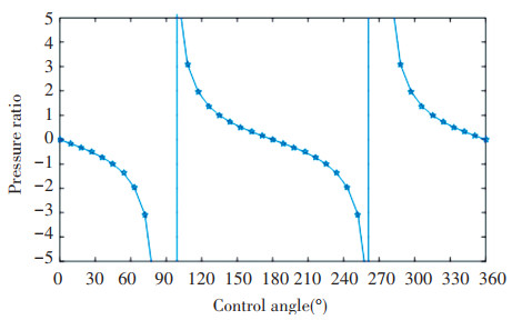
The pressure ratio formula of the four port IHT is solved, and the pressure ratio curve of the four port IHT is obtained, as shown in Fig. 9. It can be seen that the control angle range of the four port hydraulic transformer is 90° and that of the three port hydraulic transformer is 120°. Therefore, the transformation gradient of the four port hydraulic transformer is larger than that of the three port hydraulic transformer, and the response of the pressure ratio is more sensitive.
|
Fig.9 Variable pressure ratio of four port distribution plate's distribution nozzles |
4 Analysis on the Characteristics of 5-Ports Hydraulic Transformer
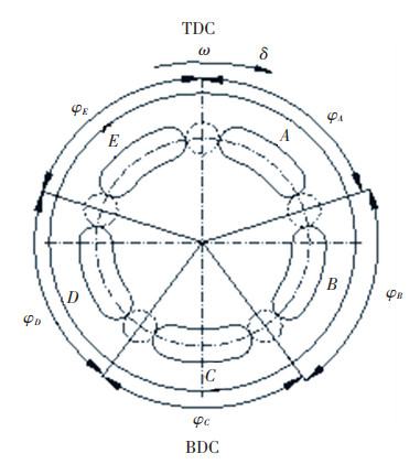
The distribution board of the IHT is divided into five sections, which constitutes the integrated 5-port hydraulic transformer. The end face of distribution plate of 5-ports IHT is shown in Fig. 10.
|
Fig.10 End face drawing of port 5 valve plate |
The starting and stopping angles of each port are brought into the plunger displacement formula 1 of the axial plunger type hydraulic components. The formula of the geometric displacement of the 5-port IHT is obtained by multiplying the plunger displacement by the area of the plunger.
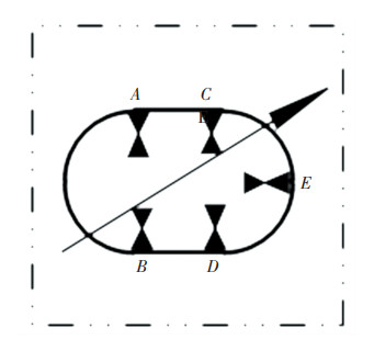
The functional symbols of the 5-port IHT is shown in Fig. 11.
| $ \left\{\begin{aligned} V_{A}=&(\pi / 4) d^{2} z R \tan k\left(\cos \left(\delta+0.5 \varphi_{A}\right)-\right.\\ &\left.\cos \left(\delta-0.5 \varphi_{A}\right)\right) \\ V_{B}=&(\pi / 4) d^{2} z R \tan k\left(\cos \left(\delta+0.5 \varphi_{A}+\varphi_{B}\right)-\right.\\ &\left.\cos \left(\delta+0.5 \varphi_{A}\right)\right) \\ V_{C}=&(\pi / 4) d^{2} z R \tan k\left(\cos \left(\delta+0.5 \varphi_{A}+\varphi_{B}+\varphi_{C}\right)-\right.\\ &\left.\cos \left(\delta+0.5 \varphi_{A}+\varphi_{B}\right)\right) \\ V_{D}=&(\pi / 4) d^{2} z R \tan k\left(\operatorname { c o s } \left(\delta+0.5 \varphi_{A}+\varphi_{B}+\varphi_{C}+\right.\right.\\ &\left.\left.\varphi_{D}\right)-\cos \left(\delta+0.5 \varphi_{A}+\varphi_{C}+\varphi_{B}\right)\right) \\ V_{E}=&(\pi / 4) d^{2} z R \tan k\left(\cos \left(\delta-0.5 \varphi_{A}\right)-\cos (\delta+\right.\\ &\left.\left.0.5 \varphi_{A}+\varphi_{C}+\varphi_{B}+\varphi_{D}\right)\right) \end{aligned}\right. $ | (11) |
|
Fig.11 Functional symbols of five-port IHT |
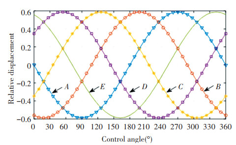
The numerical solution of the displacement of each port shows the curve as shown in Fig. 12. The positive value of the relative displacement represents that the plunger discharges oil to the corresponding port, and the negative value of the relative displacement represents that the plunger absorbs oil from the corresponding port. When the control angle of the hydraulic transformer is zero, the displacement of port A is zero. It can be seen from Fig. 10 that when the control angle is zero, the area of port A on both sides of the upper and lower dead point line is equal, the displacement of the plunger entering port A and leaving port A is equal, and the displacement difference is zero, so the relative geometric displacement is zero. The maximum displacement is 58.78% of the displacement of the base element.
|
Fig.12 Relative geometric displacement of each port of five-port IHT |
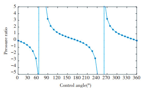
It can be seen from Fig. 12 that the negative displacement represents the working condition of the hydraulic motor and the input power, and the positive displacement represents the working condition of the hydraulic pump and the output power and flow. Considering the constant working condition, i.e., the working state of each port in the control angle range is fixed, it can be seen from Fig. 12 that when the control angle is between 0° and 72°, the displacement of port E monotonically changes to zero, and the displacement of port A monotonically changes from zero to negative. Set the control angle of the 5-port hydraulic transformer to 72°, set the output to port E and the input to port A. The formula of pressure ratio of 5-port hydraulic transformer is obtained as follows:
| $ \begin{array}{l} {\lambda _5} = \\ \frac{{\frac{\pi }{4}{d^2}zR\tan k\left( {\cos \left( {\delta + \frac{{{\varphi _A}}}{2}} \right) - \cos \left( {\delta - \frac{{{\varphi _A}}}{2}} \right)} \right)}}{{\frac{\pi }{4}{d^2}zR\tan k\left( {\cos \left( {\delta - \frac{{{\varphi _A}}}{2}} \right) - \cos \left( {\delta + \frac{{{\varphi _A}}}{2} + {\varphi _C} + {\varphi _B} + {\varphi _D}} \right)} \right)}} \end{array} $ | (12) |
The pressure ratio formula of 5-port IHT is solved, and the pressure ratio curve of 5-port IHT is obtained, as shown in Fig. 13. It can be seen that the control angle range of the 5-port hydraulic transformer is 72°, the control angle range of the 3-port hydraulic transformer is 120°, and the control angle range of the 4-port hydraulic transformer is 90°. Therefore, the transformation gradient of the 5-port hydraulic transformer is larger than that of the 3-port and 4-port hydraulic transformers, and its pressure ratio response should be more sensitive.
|
Fig.13 Pressure ratio of five port IHT |
5 Experimental Test of Pressure Ratio of IHT
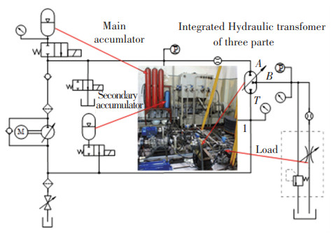
In the CPR hydraulic system, the three ports of the transformer are as follows: port A is connected to the high-pressure oil circuit, port B is connected to the low-pressure oil circuit, and port T is connected to the oil tank. In order to test the parameters of the three port IHT, the hydraulic system schematic diagram of the hydraulic experimental platform is shown in Fig. 14.
|
Fig.14 Schematic diagram of experimental system for three-port IHT |
The principle prototype of the 4-port IHT and the schematic diagram of its experimental system are shown in Fig. 15. In the hydraulic system circuit, port A of the 4-port hydraulic transformer is connected with the power oil source; port T is connected with the low-pressure oil supplement source; port O is the pressure transformation control port, connected with the load simulation; port B is the oil return port, which directly flows back to the oil tank.

|
Fig.15 Schematic diagram of experimental system for four-port IHT |
The experimental test curves of pressure ratio of the 3-ports IHT and 4-ports IHT are shown in Fig. 16. It can be seen that the curve of the measured transformation pressure can be consistent with the trend of the simulation results, but the measured pressure ratio is smaller than the theoretical pressure ratio. Because the cylinder body of the IHT needs to rotate to realize the transformation pressure, there is a loss of mechanical efficiency in the rotation of the cylinder body, and there is a loss of leakage in the three friction pairs. When the discharge of the outlet port is close to zero, the flow will leak out from all three friction pairs, and even the high pressure cannot be established. Therefore, the small discharge condition should be avoided, and the change range of the 4-ports IHT's control angle is 0-90°, which is greater than the change gradient of the pressure ratio of the three port hydraulic transformer. When the control angle is close to the maximum value, the actual pressure ratio is much smaller than the theoretical pressure ratio, because the outlet displacement is close to zero at this time and there is internal leakage in the structure. Even the high pressure cannot be established, so the small displacement condition should be avoided.

|
Fig.16 Pressure ratio of 3-ports and 4-ports IHT |
6 Conclusions
In this paper, the voltage transformation characteristics of the IHT with different port numbers were simulated and analyzed. Three port IHT and four port IHT were designed and manufactured. Based on the experimental platform, the performance of the transformer ratio was tested.
With the increase of port number, the gradient of transformer ratio of hydraulic transformer increases, i.e., the range of control angle became smaller, and the pressure gain and response speed of transformer ratio were improved.
With the increase of port number, the displacement of each port was smaller and smaller than that of the base element. The maximum displacement of each port was 86.6% of the base element. The maximum displacement of each port was 70.7% of that of the base element. The maximum displacement of each port was 58.78% of that of the base element.
In theory, the pressure ratio of the hydraulic transformer can be very large, but in fact, because the discharge capacity at the outlet was very small at this time and because of the existence of internal leakage, the outlet pressure of the hydraulic transformer did not continue to rise, so we should prevent the port from working under the condition of small discharge capacity.
The increase of port will make the plunger frequently transition between different ports in a cycle, which will make the noise of the hydraulic transformer larger and the efficiency lower. At the same time, the switch between oil suction and oil discharge conditions of each port is more frequent, so the increase of port number is not good for the IHT.
| [1] |
Achten P A J, Zhao F, Vael G E M. Transforming future hydraulics: a new design of a hydraulic transformer. The Fifth Scandinavian International Conference on Fluid Power (SICFP '97). Sweden: Linköing, 1997: 287ev.
(  0) 0) |
| [2] |
Vael G E M, Achten P A J, Zhao F. The innas hydraulic transformer-the key to the hydrostatic common pressure rail. International Off-Highway & Powerplant Congress & Exposition. Warrendale, PA, USA: SAE International. 1-16. DOI: 10.4271/2000-01-2561.
(  0) 0) |
| [3] |
Achten P. Variable hydraulic transformer. Design News, 2002, 58(17): 48. (  0) 0) |
| [4] |
Vael G E M, Achten P A J. IHT Controlled Serial Hydraulic Hybrid Passenger Cars. Proceedings of the 7th International Fluid Power Conference. Aachen: University of Parma, 2010: 393-405.
(  0) 0) |
| [5] |
Ouyang X P. Research on the Hydraulic Transformer Hangzhou: Zhejiang University, 2005.
(  0) 0) |
| [6] |
Ouyang X P, Yang H Y, Xu B, et al. Research on the hydraulic transformer with new distribution pairs. Science in China Series E: Technological Sciences, 2008, 51(4): 435-442. DOI:10.1007/s11431-008-0030-z (  0) 0) |
| [7] |
Ma J, Bing X, Zhang B, et al. Experiment study on working performance of hydraulic transformer.Proceedings of the Fifth International Symposium on Fluid Power Transmission and Contro. Qinghuangdao, Hebei, 2007, 06: 111-115. (  0) 0) |
| [8] |
Liu T, Gong G F, Peng Z. Hybrid cutterhead driving system for TBM based on hydraulic transformer. Journal of Zhejiang University (Engineering Science), 2016, 50(3): 419-427. DOI:10.3785/j.issn.1008-973X.2016.03.004 (  0) 0) |
| [9] |
Hung H T, Kwan A K. A study on the position control of hydraulic cylinder driven by hydraulic transformer using disturbance observer. International Conference on Control, Automation and Systems 2008. Piscataway: IEEE, 2008. DOI:10.1109/ICCAS.2008.4694301
(  0) 0) |
| [10] |
Ho T H, Kwan A K. Saving energy control of cylinder drive using hydraulic transformer combined with anassisted hydraulic circuit. ICROS-SICE International Joint Conference 2009. Piscataway: IEEE, 2009: 2115-2120.
(  0) 0) |
| [11] |
Yu Y X, Kwan A K. Application of hydraulic transformer on energy saving for boom system of hybrid hydraulic excavator. Applied Mechanics & Materials, 2017, 868: 118-123. DOI:10.4028/www.scientific.net/AMM.868.118 (  0) 0) |
| [12] |
Lu H Y. Theoretical Analysis and Experiment of Electric Control Bent Axial Piston Hydraulic Transformer. Harbin: Harbin Institute of Technology, 2008.
(  0) 0) |
| [13] |
Lu H Y, Jiang J H, Zhang W G, et al. Hydraulic transformer driving hydraulic cylinder based on constant-pressure hydraulic rail system. Journal of Jilin University (Engineering and Technology Edition), 2009, 39(4): 885-890. DOI:10.13229/j.cnki.jdxbgxb2009.04.013 (  0) 0) |
| [14] |
Shi M S, Liu H W, Li W, et al. Tidal current turbine hydraulic transmission system based on hydraulic transformer. Journal of Zhejiang University (Engineering Science), 2014, 48(5): 764-769, 783. DOI:10.3785/j.issn.1008-973X.2014.05.002 (  0) 0) |
| [15] |
Liu C Q, Jiang J H. Effect of plunger number on hydraulic, transformer's flow pulsation rate. High Technology Letters, 2013, 19(1): 30-36. DOI:10.3772/j.issn.1006-6748.2013.01.006 (  0) 0) |
| [16] |
Jiang J H, Yang G Z. Development and research status of hydraulic transformer in hydraulic system. Journal of Chang'an University (Natural Science Edition), 2016, 36(6): 118-126. DOI:10.19721/j.cnki.1671-8879.2016.06.016 (  0) 0) |
| [17] |
Yang G Z, Jiang J H. Power characteristics of a variable hydraulic transformer. Chinese Journal of Aeronantics, 2015, 28(3): 914-931. DOI:10.1016/j.cja.2015.04.008 (  0) 0) |
| [18] |
Yang G Z, Jiang J H. Flow characteristics of variable hydraulic transformer. Journal of Central South University, 2015, 22: 2137-2148. DOI:10.1007/s11771-015-2738-9 (  0) 0) |
| [19] |
Liu S A, Xie D T, Shang T, et al. Control strategy of the value plant of hydraulic transformer based on fractional order PID controller. Journal of Beijing University of Technology, 2013, 39(10): 1452-1458. (  0) 0) |
| [20] |
Wu W, Jing C B, Hu J B, et al. Characteristics of dual-cylinder hydraulic transformer with rotatable wash plate. Journal of Mechanical Engineering, 2013, 49(22): 144-149. DOI:10.3901/JME.2013.22.144 (  0) 0) |
| [21] |
Zhao H M, Wu W, Hu J B, et al. Characteristics of hydraulic transformer controlled hydraulic motor system. Transactions of Beijing Institute of Technology, 2017, 37(5): 441-445. DOI:10.15918/j.tbit1001-0645.2017.05.001 (  0) 0) |
| [22] |
Wu W, Di C F, Hu J B, et al. Adaptive reverse driving system based on hydraulic transformer. Journal of Jilin University (Engineering and Technology Edition), 2016, 46(6): 1906-1911. DOI:10.13229/j.cnki.jdxbgxb201606020 (  0) 0) |
| [23] |
Jing C B, Zhou J J, Yuan S H, et al. Research on the pressure ratio characteristics of a swash plate-rotating hydraulic transformer. Energies, 2018, 11(6): 1612. DOI:10.3390/en11061612 (  0) 0) |
| [24] |
Li H Y, Ning C M, Chen S S, et al. Analysis of hydraulic luffing system of armored recovery vehicle based on hydraulic transformer. Journal of Academy of Armored Force Engineering, 2018, 32(6): 56-62. DOI:10.3969/j.issn.1672-1497.2018.06.010 (  0) 0) |
| [25] |
Ning C M, Chao Z Q, Han S S, et al. Energy-saving research of hydraulic system based on hydraulic transformer. Machine Tool & Hydraulics, 2017, 45(13): 61-67. DOI:10.3969/j.issn.1001-3881.2017.13.015 (  0) 0) |
| [26] |
Shen W, Jiang J H, Wang K L. Dynamic analysis of boom system based on hydraulic transformer. Transactions of the Chinese Society for Agricultural Machinery, 2013, 44(4): 27-32. DOI:10.6041/j.issn.1000-1298.2013.04.005 (  0) 0) |
| [27] |
Shen W, Wang J H, Huang H L, et al. Fuzzy sliding mode control with state estimation for velocity control system of hydraulic cylinder using a new hydraulic transformer. European Journal of Control, 2019, 48: 104-114. DOI:10.1016/j.ejcon.2018.11.005 (  0) 0) |
| [28] |
Shen W, Karimi H R, Zhao R H. Comparative analysis of component design problems for integrated hydraulic transformers. The International Journal of Advanced Manufacturing Technology, 2019, 103: 389-407. DOI:10.1007/s00170-019-03543-2 (  0) 0) |
| [29] |
Shen W, Wang J H. A robust controller design for networked hydraulic pressure control system based on CPR. Peer-to-Peer Networking and Applications, 2019, 2: 1651-1661. DOI:10.1007/s12083-019-00760-0 (  0) 0) |
| [30] |
Gaspar J F, Calvário M, Kamarlouei M, et al. Power take-off concept for wave energy converters based on oil-hydraulic transformer units. Renewable Energy, 2016, 86: 1232-1246. DOI:10.1016/j.renene.2015.09.035 (  0) 0) |
 2021, Vol. 28


