2. Jiangsu Automation Research Institute, Jiangsu Lianyungang 222061, China;
3. China Academy of Launch Vehicle Technology, Beijing 100076, China;
4. Shanghai Aircraft Design and Research Institute, Shanghai 200232, China
With the development of nanotechnology[1], the sizes of the mechanical components come to a scale of nanometers. At nanoscale, adhesion effects are predominant between contact surfaces, and the friction behaviors are quite different from the macroscopic tribology[2]. Nanoscale friction involves complex energy exchange[3], and the friction energy mainly contributes to the frictional heat[4]. Especially, in nanoscale sliding contacts, the high friction forces could induce a high temperature on the interface. In addition, the frictional heat can make the material become soft or even melt[5], and affects friction behaviors. Therefore, friction behaviors of nanoscale sliding contacts should be studied considering the frictional heat.
There are many experimental studies on the friction properties of nanoscale sliding contacts, while it is hard to perform a real-time monitor on the interface behaviors. Molecular dynamics (MD) simulation can extract information that is difficult to measure in experiments, such as temperature[6], which is widely used to investigate the nanotribology. Sliding contacts are influenced by the sliding velocity and the tip size. On the one hand, at different sliding velocities, atoms accumulation is different, which affects the ploughing component. Moreover, the surface structure could be changed by the atoms accumulation, and the adhesion component will be affected for different contact areas induced by the surface structures. Besides, the contact area is also influenced by the tip size, which affects the adhesion component, and the friction forces will be influenced further.
The influence of sliding velocity was widely investigated. For the sliding velocities used in Ref.[7], the authors found that there is nearly no relationship between coefficients of friction (COFs) and velocity. A linear relationship between friction force and the logarithm of the velocity is presented in Ref. [8], which agrees with the experimental results, while their results are not suitable for the case of high velocities. To avoid the shortcoming, Sang et al.[9] suggested an exponential relationship, which covers a wide range of applications. Li et al.[10] performed friction force microscopy experiment and MD simulation to investigate friction behaviors of gold surfaces. At a low velocity range, the friction force increases approximately linearly as sliding velocity, while stable friction forces are shown when velocity increases to a certain value. Using MD simulation, Wang and Li[11] also pointed out that the friction force increases logarithmically relative to sliding velocity for the friction of two graphite sheets. On the contrary, when Sørensen et al.[12] slid a copper probe on a copper substrate, they found that increasing sliding velocity leads to a decrease in friction. Fajardo et al.[13] discovered that friction force increases with sliding velocity when the temperature is higher than a certain value, and it decreases with increasing sliding velocity for a low temperature. Piroozan et al.[14] investigated the friction behaviors between the SiC surfaces. The friction force decreases with increasing sliding velocity, and the authors attributed the friction reduction to bond breaking in SiC surfaces. Bai et al.[15] pointed out that sliding depth of the tip and the interface bonds are reduced at high velocities, which contributes to the friction reduction. The number of bonds at contact interface will be different for different tip sizes, and influences the friction behaviors.
Considering the tip size effects, the friction characteristics of the sliding contacts have been investigated extensively. Chandross et al.[16] studied the friction behaviors of alkylsilane SAMs on amorphous SiO2 by MD simulations. Friction force is higher for the tip with a bigger radius. AFM and SFM experiments were carried out to investigate friction behaviors of silicon with nano textured surfaces, and the COF increased with tip radius[17]. Friction characteristics in nanoscale sliding contacts between cylindrical tips and textured surfaces were studied by multiscale method[18], and friction forces showed higher values when the radius was bigger. Lee et al.[19] studied friction properties between phosphorene and silicon tip by MD simulations. The average friction force (AFF) is enhanced as tip size increases, and the authors attributed it to contact area increasing. Pang et al.[20] investigated a nanoscale sliding contact of a single-layer molybdenum disulfide by MD simulations. Friction force increases with the tip size, and the amplitudes for the tips with radii from 1 to 2 Å are much lower compared with the tips with radii from 4 to 10 Å. Nanoscale impact friction behaviors of copper were studied in Ref.[21]. A big tip induces a large contact area that produces a high friction force. Using simulated friction force microscopy, Smolyanitsky[22] studied the friction properties of the suspended graphene. The normalized friction force of a bigger tip is lower than the case of a smaller tip. Sliding processes of an AFM tip on rigid dodecagonal or honeycomb silicone were simulated by MD simulations[23], and AFFs were reduced with increasing tip size. Zhu et al.[24] studied nanometric scratching of FCC Cu by MD simulations. They found that a blunt tip produces a higher COF than a sharp tip when the radii of the tips are smaller, while the bigger tips show a reversed trend. Therefore, the tip size also presents different effects on the friction behaviors, and it should produce the corresponding influence on the interface temperature which needs to be investigated further.
The sliding velocity and the tip size influence the friction force, and affect frictional heat and temperature rise. Moreover, the temperature will affect the thermal motion of atoms, which further influences the mechanical properties[25] or the friction force. Bai et al.[26] studied the friction behaviors between Si and diamond by MD simulation, and reported that a high sliding velocity leads to a low friction force, because a high velocity usually leads to a high contact temperature, which makes Si layer melt to reduce friction force. Under different velocities, friction behaviors and interface temperatures affect each other. Similarly, for different tip sizes, the friction behaviors and the interface temperatures will also influence each other. During the MD simulation on nanoscale Si machining, for the cutting tool with large V-shape textures, the tool temperature was increased, and the cutting force was reduced[27]. Therefore, when the effects of sliding velocity and tip size on friction behaviors are studied, the thermal effects should be coupled.
Considering the interaction between the friction behaviors and the interface temperatures, a nanoscale sliding contact model is proposed by MD simulation. Thermal and friction properties of FCC copper are studied, different sliding velocities and tip radii are considered and their influence is discussed.
1 Modelling 1.1 MD ModelThe MD model used in this paper is given in Fig. 1, including a rigid cylindrical tip and an elastic substrate. The system material is FCC copper. The dimension of the substrate is 180 Å (x direction)×29 Å (y direction)×90 Å (z direction), and the tip length is 29 Å in y direction. For the substrate, the bottom 3 layers atoms are fixed, and the 3 layers atoms above the fixed atoms are the thermostatic atoms whose temperatures are kept at 300 K. The Nosé -Hoover[28] method is applied in the thermostatic atoms to control temperatures. Besides the thermostatic atoms and fixed atoms, the rest atoms of the substrate are Newtonian atoms. To study thermal characteristics of this system, the Newtonian atoms are divided into 11 layers from top to bottom, h1-h11, respectively. Considering that the atoms on the top of the substrate could be worn during the sliding contact, there are 5 layers atoms in h1 layer in z direction. For h2-h11 layers, the thickness of each layer is 4 layers atoms in z direction. A periodic boundary condition is applied in x and y directions, and a non-periodic boundary condition is applied in z direction. The crystal orientations are [1 0 0], [0 1 0], and [0 0 1] corresponding to x, y and z directions.

|
Fig.1 Molecular dynamics model of a sliding contact |
An EAM potential[29] is applied to the system in this paper:
| $ E_{\mathrm{tot}}=\sum\limits_{i=1}^{N}\left[F\left(\rho_{i}\right)+0.5 \sum\limits_{j=1, j \neq i}^{N} \varPhi\left(r_{i j}\right)\right] $ | (1) |
| $ \varPhi\left(r_{i j}\right)=A_{1}\left(r_{c 1}-r_{i j}\right)^{2} \mathrm{e}^{-c 1 r_{i j}} $ | (2) |
| $ F\left(\rho_{i}\right)=D \rho_{i} \ln \rho_{i} $ | (3) |
| $ \rho_{i}=\sum\limits_{j=1, j \neq i}^{N} f\left(r_{i j}\right) $ | (4) |
| $ f\left(r_{i j}\right)=A_{2}\left(r_{c 2}-r_{i j}\right)^{2} \mathrm{e}^{-c 2 r_{i j}} $ | (5) |
where Etot is the total energy, ρi represents background electron cloud superposition at atom i, F(ρi) represents embedding energy, Φ(rij) represents a pairwise interaction potential, and f(rij) represents density of electron cloud induced by atom j at the distance rij. Besides, A1 represents Born stability, A2 represents cohesive energy, c1 represents elastic constants, c2 represents formation energy of a vacancy, and D represents stacking fault energy. For FCC Cu,
| $ A_{1}=8.2894599770489921 \times 10^{3} $ |
| $ A_{2}=1.832510350693439 \times 10^{-2} $ |
| $ c_{1}=1.07272912864108215 \times 10^{1} $ |
| $ c_{2}=3.19759369823463370 \times 10^{-1} $ |
| $ D=1.30792125162800630 \times 10^{1} $ |
The essence of temperature is the average kinetic energy contributed by the thermal motion of atoms. The kinetic energy calculated by MD simulation contains atom thermal kinetic energy and centroid translational kinetic energy. Therefore, when calculating the temperature, one should subtract the translational velocity of the centroid. In order to study the thermal properties, the substrate is divided into many groups[30-32]. For each group, the total kinetic energy is
| $ \left(E_{k}\right)_{\mathrm{tot}}=0.5 \sum m_{i}\left(v_{i x}^{2}+v_{i y}^{2}+v_{i z}^{2}\right) $ | (6) |
where vix, viy, viz represent velocities of atom i in the corresponding directions, respectively, and mi represents the mass of atom i.
Centroid translational kinetic energy of one group can be obtained as
| $ \left(E_{k}\right)_{c . t}= 0.5 \sum m_{i}\left(\bar{v}_{x}^{2}+\bar{v}_{y}^{2}+\bar{v}_{z}^{2}\right) $ | (7) |
| $ \bar v_{x} =k^{-1} \sum v_{i x} $ | (8) |
| $ \bar v_{y} =k^{-1} \sum v_{i y} $ | (9) |
| $ \bar v_{z} =k^{-1} \sum v_{i z} $ | (10) |
in which k represents the number of atoms that have translational motion in each group.
Thermal energy of each atom is
| $ \left(E_{k}\right)_{j}=n^{-1}\left[\left(E_{k}\right)_{\mathrm{tot}}-\left(E_{k}\right)_{c . t}\right] $ | (11) |
in which n represents the number of all atoms in each group, and final temperature is
| $ T_{j}=2\left(E_{k}\right)_{j} /\left(3 k_{B}\right) $ | (12) |
where kB represents Boltzmann constant.
1.3 Simulation ProcessIn this work, LAMMPS[33] was utilized to study nanoscale sliding contact problems, and the results were post-processed by OVITO[34]. For all MD simulations, velocity-Verlet algorithm was carried out, and a time step, Δt=0.001 ps was utilized. Before loading, velocities of all atoms except the fixed ones were initialized. During initialization, a NVT ensemble was used, and system temperature was kept at 300 K. Then the system energy was minimized by running 10 ps. After that, a NVE ensemble was introduced to the Newtonian atoms. To avoid the influence of the tip atoms on the substrate atoms when the system energy is minimized, the original gap between the tip and substrate was set as ds=7.2 Å (ds>rc, rc is a cut-off radius, and rc=4.95 Å). At the beginning of loading, the tip was moved down to the substrate for 6.87 Å with a velocity of v0=100 m/s, and this process was applied to all the simulations in this work. After loading, the tip began to slide in x direction. If the tip came to right boundary, a continued sliding would make it enter from the left boundary due to the periodic boundary condition, and the tip was slid for 831 Å in x direction at a fixed sliding velocity.
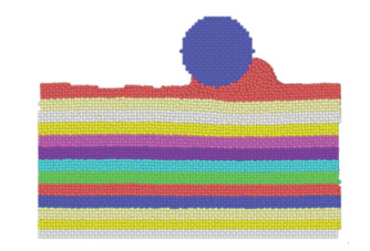
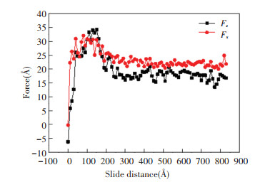
2 Results and Discussion 2.1 Friction and Thermal Properties for v=200 m/sIn this section, the tip slides on the substrate at a velocity of 200 m/s, and the radius of the rigid cylindrical tip is R=21.7 Å. Fig. 2 is the atomic image corresponding to a sliding distance of 60 Å. Fig. 3 shows the friction forces Fx and normal forces Fz with sliding distance of the tip. From Fig. 3, Fx and Fz increase greatly at initial phase during sliding process, because the tip scratches substrate, which makes many atoms accumulate in front of the tip, as shown in Fig. 2. Considering adhesion and ploughing effects on a friction force[35], the accumulated atoms produce a large contact area, which results in the increase of adhesion effects. Besides, atoms in front of the tip enhance ploughing effects, so friction forces show high values. From the view of energy, due to the accumulated atoms, the substrate atoms are sheared during the sliding process, which deforms the lattice. The energy is generated by shearing existing in the form of lattice strain energy, and it is increased gradually. When lattice strain energy in the crystal equals to binding energy of atomic bonds in the substrate, the atomic bonds are destroyed. The energy is released then, and the crystal lattice will be arranged in a new form. Therefore, the friction and normal forces at initial stage fluctuate greatly. The friction and normal forces reach maximum values when the tip slides to 150 Å, and then the forces decrease gradually. When the tip slides to 300 Å, the friction force is maintained around 22 ev/Å, and the normal force is maintained around 18 ev/Å. To explain the decrease of friction and normal forces, temperature evolution in the layers of the substrate should be studied.
|
Fig.2 Atomic image of the sliding process (R=21.7 Å, v=200 m/s) |
|
Fig.3 Friction and normal forces (R=21.7 Å, v=200 m/s) |
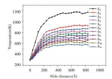
Fig. 4 shows the average temperature fluctuation of the h1-h11 layers. At initial phase, temperatures show little difference among the layers of the substrate, and the heat conduction is slow, so the substrate temperature accumulates and increases greatly. After this phase, temperature difference between the layers becomes greater, and the heat conduction increases. The increase rate of the substrate temperature gradually decreases until frictional heat generation and heat dissipation reach a thermal equilibrium, and then the temperature is maintained at nearly a constant value. From Fig. 4, there are obvious temperature gradients between atomic layers and the temperature difference decreases from top to bottom. The closer to the thermostatic atoms, the faster the atomic layer reaches thermal equilibrium.
|
Fig.4 Temperatures of h1-h11 layers (R=21.7 Å, v= 200 m/s) |
The substrate temperature distribution is shown in Fig. 5 when the tip slides to 300 Å. A high temperature area locates around the tip in x direction and a highest temperature reaches 1375 K, which will make the local material melt. Corresponding to Fig. 5, an atomic defect map is shown in Fig. 6, and a CNA method[36-37] is employed to discriminate atomic defects. Atoms are colored based on the CNA value calculated by this method. The orange atoms are the FCC structure, and the CNA value is 1. The yellow atoms represent the atoms with defects, and the CNA value is 5. Combining Fig. 5 and Fig. 6, atoms under or in front of the tip are all yellow, which means that this area is a local melting area caused by the high temperature. This local melting area acts as the lubricant, and friction forces present a stable low level in Fig. 3 from 300 Å.

|
Fig.5 Substrate temperature distribution (R=21.7, v=200 m/s) |

|
Fig.6 Atomic defect map (R=21.7 Å, v=200 m/s) |
According to the temperature contour, the distribution of the temperature and the heat transfer can be observed clearly. Near the contact area, the temperature changes greatly and the heat is transferred to the surroundings. In the substrate far from contact region, the heat is conducted towards bottom thermostatic atoms.
2.2 Friction and Thermal Properties at Different VelocitiesWhen the tip radius is R=21.7 Å, Fig. 7 compares average temperatures of the substrate at different velocities. Here, average temperature represents an average value of all Newtonian atoms in the substrate. When the sliding velocity is 5 m/s, less heat is generated in the sliding process due to a lower sliding velocity, and the heat is dissipated by being transferred to the thermostatic atoms, so the temperature is maintained at about 303 K. When v=20 m/s, the substrate temperature increases slightly, and the equilibrium temperature is around 325 K. At a higher sliding velocity (100 m/s or 200 m/s), much more heat will be generated, and only part of the heat can be dissipated by heat conduction, which results in the increase of substrate temperature.

|
Fig.7 Average temperature of the substrate at different sliding velocities (R=21.7 Å) |
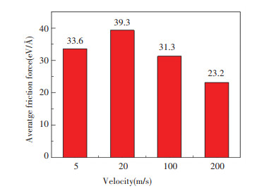
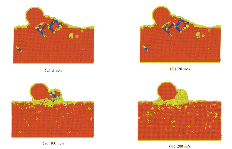
The average friction forces (AFFs) under different velocities are compared in Fig. 8. At lower sliding velocities (5 or 20 m/s in this paper), the AFF increases with velocity. When the velocity reaches a certain value (20 m/s), the AFF begins to decrease, and the temperature rise should be the reason for the decrease. According to the work of Sørensen et al.[12], for a copper probe sliding along a copper crystal surface, the friction force decreases when velocity increases. However, this phenomenon is just the opposite in this paper when the velocity is changed from 5 to 20 m/s. To explain this phenomenon of the increase of friction force, atomic defect maps with a sliding distance of 300 Å are presented in Fig. 9. The orange atoms are the FCC structure whose CNA value is 1. The blue ones represent an HCP lattice, which means the formation of dislocations[38], and the CNA value is 2. The yellow atoms represent the atoms with defects, and the CNA value is 5. In Fig. 9(a) and Fig. 9(b), there are many atoms accumulating around or in front of the tip, which induce the enhancement of real contact area and adhesion component. Besides, atoms in front of the tip result in the increase of ploughing component. According to Ref.[35], the friction force consists of these typical components, so these increased components induce a high AFF. For higher velocities, high temperature induced by sliding makes the atoms of substrate melt. In Fig. 9(c) and Fig. 9(d), many yellow atoms are presented under the tip, which means the local contact region has been melted. With the increase of temperature, the mechanical strength of the structure reduces greatly[39]. The melted atoms make the material soft, and the shear strength is reduced, which contributes to the decrease of AFF and induces a lowest AFF for the case of v=200 m/s.
|
Fig.8 Average friction forces under different velocities (R=21.7 Å) |
|
Fig.9 Atomic defect maps at different sliding velocities (R=21.7 Å) |
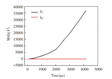
Fig. 10 shows mean-square displacement (MSD) of the h1 and h2 layers when v=20 m/s. From Fig. 10, the MSD of h1 layer increases with the sliding time before 2000 ps, while the MSD of the h2 layer is almost 0. When the sliding time reaches 2000 ps, a linear relationship is shown between the MSD and time, which indicates that part of the h1 layer has been melted. The melted part is rapidly solidified due to the low ambient temperature, resulting in more material bondings. A higher force will be needed for the tip to overcome the material deformation, so at 20 m/s there are more dislocations than those in the case of 5 m/s and the AFF is also higher.
|
Fig.10 MSD of h1 and h2 layers when the velocity is 20 m/s |
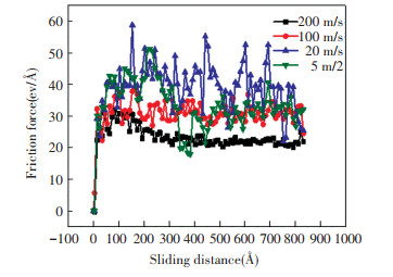
Fig. 11 shows friction forces under four sliding velocities. The friction forces at 5 and 20 m/s show a distinct difference after 380 Å. When the tip comes to 380 Å at 5 m/s, it is equivalent to the tip slides over the substrate for the third time. The first two sliding processes have caused wear of the substrate and new material migration no longer occurs, so the friction forces fluctuate in a small range around 31 eV/Å. For the case of 20 m/s, the wear mechanism of the substrate surface before the sliding distance of 380 Å is similar to that of 5 m/s. When the tip comes to 380 Å, it corresponds to 2000 ps in Fig. 10. The melting-solidification of the materials continues occurring, so the friction forces fluctuate severely after 380 Å. Since a high velocity sliding process generates a large amount of heat, when the sliding velocities are 100 or 200 m/s, a melted region under the tip causes the friction forces to decrease after 150 Å, and the friction forces fluctuate around low values when the tip comes to 380 Å.
|
Fig.11 Friction forces at different velocities (R=21.7 Å) |
2.3 Effects of Tip Radii on Friction and Thermal Properties
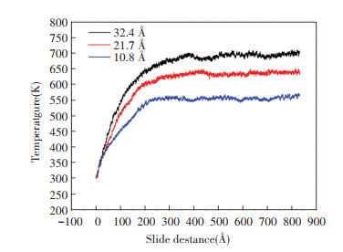
Fig. 12 gives average temperatures when the tip radii are 10.8 Å, 21.7 Å, and 32.4 Å. The equilibrium temperature increases with increasing tip radius. When the radius is increased, the contact area and adhesive force will be increased, which results in an increased friction force and induces more frictional heat. As a result, there is a high equilibrium temperature for a big tip.
|
Fig.12 Average temperatures of substrate for different tip radii (v=100 m/s) |
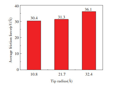
Fig. 13 presents AFFs for different tip radii at the velocity of 100 m/s. The AFF increases with the tip radius. For one thing, adhesion component is proportional to the contact area, and increasing the tip radius increases contact area, which enhances adhesion component. For another, a bigger radius makes more atoms accumulate, which increases ploughing component. Thus, these factors should make a high AFF when tip radius is increased. On the contrast, the substrate temperature is also enhanced with increasing tip radius, and substrate material should be soft or melted, which has a trend to decrease the friction force. As a result, the tip radius and the substrate temperature produce coupled effects, and the increase rate of the AFF for different tip radii is low according to Fig. 13.
|
Fig.13 Average friction forces for different tip radii (v=100 m/s) |
3 Conclusions
In this paper, nanoscale thermal sliding contact problems are studied by MD simulation. Friction and thermal properties under different sliding velocities are analyzed. Besides, tip radius effects on temperature and friction force are studied.
(1) Friction behaviors in high velocity sliding process and low velocity sliding process are different. The friction force fluctuation at a low velocity is mainly caused by the material melting-solidification of the substrate. For a high velocity sliding process, the friction mechanism is similar to that of a low velocity at the initial stage, and the subsequent friction reduction is mainly caused by local melting of the substrate.
(2) When the velocity is changed from 5 to 20 m/s, a melting-solidification phenomenon on the substrate and accumulated atoms increase AFFs. Increasing the sliding velocity to 100 m/s, a stable melting layer between the substrate and the tip is formed, so AFFs are decreased. Further increasing velocity leads to decreased AFFs.
(3) Increasing the tip radius can enhance the substrate temperature for the case of 100 m/s, and the increasing temperature should reduce the AFFs, while the AFFs are increased on the contrary due to high adhesion components caused by the large contact areas for the big tip.
| [1] |
Bhushan B. Nanotribology and nanomechanics of MEMS/NEMS and BioMEMS/BioNEMS materials and devices. Microelectronic Engineering, 2007, 84(3): 387-412. DOI:10.1016/j.mee.2006.10.059 (  0) 0) |
| [2] |
Barel I, Urbakh M, Jansen L, et al. Temperature dependence of friction at the nanoscale: when the unexpected turns normal. Tribology Letters, 2010, 39: 311-319. DOI:10.1007/s11249-010-9675-4 (  0) 0) |
| [3] |
Liu X M, Liu Z L, Wei Y G. Nanoscale friction behavior of the Ni-film/substrate system under scratching using MD simulation. Tribology Letters, 2012, 46: 167-178. DOI:10.1007/s11249-012-9932-9 (  0) 0) |
| [4] |
Ashby M F, Abulawi J, Kong H S. Temperature maps for frictional heating in dry sliding. Tribology Transactions, 1991, 34(4): 577-587. DOI:10.1080/10402009108982074 (  0) 0) |
| [5] |
Tong R T, Han B, Quan Z F, et al. Molecular dynamics simulation of friction and heat properties of nanotexture gold film in space environment. Surface & Coatings Technology, 2019, 358: 775-784. DOI:10.1016/j.surfcoat.2018.11.084 (  0) 0) |
| [6] |
Wen Y H, Zhu R Z, Zhou F X, et al. An overview on molecular dynamics simulation. Advances in Mechanics, 2003, 33(1): 65-73. (in Chinese) DOI:10.6052/1000-0992-2003-1-J2002-021 (  0) 0) |
| [7] |
Harrison J A, White C T, Colton R J, et al. Molecular-dynamics simulations of atomic scale friction of diamond surfaces. Physical Review B, 1992, 46(15): 9700-9708. DOI:10.1103/PhysRevB.46.9700 (  0) 0) |
| [8] |
Gnecco E, Bennewitz R, Gyalog T, et al. Velocity dependence of atomic friction. Physical Review Letters, 2000, 84(6): 1172-1175. DOI:10.1103/PhysRevLett.84.1172 (  0) 0) |
| [9] |
Sang Y, Dube M, Grant M. Thermal effects on atomic friction. Physical Review Letters, 2001, 87(17): 174301. DOI:10.1103/PhysRevLett.87.174301 (  0) 0) |
| [10] |
Li Q Y, Dong Y L, Perez D, et al. Speed dependence of atomic stick-slip friction in optimally matched experiments and molecular dynamics simulation. Physical Review Letters, 2011, 106(12): 106101. DOI:10.1103/PhysRevLett.106.126101 (  0) 0) |
| [11] |
Wang W, Li X D. Interlayer motion and ultra-low sliding friction in microscale graphite flakes. Europhysics Letters, 2019, 125(2): 26003. DOI:10.1209/0295-5075/125/26003 (  0) 0) |
| [12] |
Sørensen M R, Jacobsen K W, Stoltze P. Simulations of atomic-scale sliding friction. Physical Review B, 1996, 53(4): 2101-2113. DOI:10.1103/PhysRevB.53.2101 (  0) 0) |
| [13] |
Fajardo O Y, Barel I, Urbakh M. Friction through reversible jumps of surface atoms. Journal of Physics: Condensed Matter, 2014, 26(31): 315005. DOI:10.1088/0953-8984/26/31/315005 (  0) 0) |
| [14] |
Piroozan N, Naserifar S, Sahimi M. Sliding friction between two silicon-carbide surfaces. Journal of Applied Physics, 2019, 125(12): 124301. DOI:10.1063/1.5086185 (  0) 0) |
| [15] |
Bai L C, Srikanth N, Korznikova E A, et al. Wear and friction between smooth or rough diamond-like carbon films and diamond tips. Wear, 2017, 372-373: 12-20. DOI:10.1016/j.wear.2016.12.007 (  0) 0) |
| [16] |
Chandross M, Lorenz C D, Stevens M J, et al. Simulations of nanotribology with realistic probe tip models. Langmuir, 2008, 24(4): 1240-1246. DOI:10.1021/la702323y (  0) 0) |
| [17] |
Zhang H S, Komvopoulos K. Anisotropic frictional behavior of nanotextured surfaces. Proceedings of the STLE/ASME International Joint Tribology Conference. New York: ASME, 2008. 749-751. DOI: 10.1115/IJTC2008-71146.
(  0) 0) |
| [18] |
Tong R T, Liu G, Liu T X. Multiscale analysis on two dimensional nanoscale sliding contacts of textured surfaces. ASME Journal of Tribology, 2011, 133(4): 041401. DOI:10.1115/1.4004759 (  0) 0) |
| [19] |
Lee H G, Yoon H M, Lee J S. Anisotropic nanoscale and sub-nanoscale friction behaviors between phosphorene and silicon tip. Applied Surface Science, 2019, 481: 1573-1584. DOI:10.1016/j.apsusc.2019.01.204 (  0) 0) |
| [20] |
Pang H S, Li M L, Gao C H, et al. Characterization of frictional properties of single-layer molybdenum-disulfide film based on a coupling of tip radius and tip-sample distance by molecular-dynamics simulations. Nanomaterials, 2018, 8(6): 387. DOI:10.3390/nano8060387 (  0) 0) |
| [21] |
Tong R T, Liu G. Friction property of impact sliding contact under vacuum and microgravity. Microgravity Science and Technology, 2019, 31(1): 85-94. DOI:10.1007/s12217-018-9667-9 (  0) 0) |
| [22] |
Smolyanitsky A. Effects of thermal rippling on the frictional properties of free-standing grapheme. RSC Advances, 2015, 5(37): 29179-29184. DOI:10.1039/C5RA01581B (  0) 0) |
| [23] |
Qian C, Wang J G. Dodecagonal quasicrystal silicene: preparation, mechanical property, and friction behaviour. Physical Chemistry Chemical Physics, 2020, 22(1): 74-81. DOI:10.1039/C9CP03757H (  0) 0) |
| [24] |
Zhu P Z, Hu Y Z, Wang H, et al. Study of effect of indenter shape innanometric scratching process using molecular dynamics. Materials Science and Engineering: A, 2011, 528(13-14): 4522-4527. DOI:10.1016/j.msea.2011.02.035 (  0) 0) |
| [25] |
Subedi S, Handrigan S M, Morrissey L S, et al. Mechanical properties of nanocrystalline aluminium: a molecular dynamics investigation. Molecular Simulation, 2020, 46(12): 898-904. DOI:10.1080/08927022.2020.1788217 (  0) 0) |
| [26] |
Bai L C, Sha Z D, Srikanth N, et al. Friction between silicon and diamond at the nanoscale. Journal of Physics D: Applied Physics, 2015, 48(25): 255303. DOI:10.1088/0022-3727/48/25/255303 (  0) 0) |
| [27] |
Liu C L, Zhang J G, Zhang JJ, et al. Influence of micro grooves of diamond tool on silicon cutting: a molecular dynamic study. Molecular Simulation, 2020, 46(2): 92-101. DOI:10.1080/08927022.2019.1675884 (  0) 0) |
| [28] |
Melchionna S, Ciccotti G, Holian B L. Hoover NPT dynamics for systems varying in shape and size. Molecular Physics, 1993, 78(3): 533-544. (  0) 0) |
| [29] |
Doyama M, Kogure Y. Embedded atom potentials in fcc and bcc metals. Computational Materials Science, 1999, 14: 80-83. DOI:10.1016/S0927-0256(98)00076-7 (  0) 0) |
| [30] |
Chen K, Wang L B, Chen Y T, et al. Molecular dynamics simulation of microstructure evolution and heat dissipation of nanoscale friction. International Journal of Heat and Mass Transfer, 2017, 109: 293-301. DOI:10.1016/j.ijheatmasstransfer.2017.01.105 (  0) 0) |
| [31] |
Dai H F, Li S B, Chen G Y. Comparison of subsurface damages on mono-crystalline silicon between traditional nanoscale machining and laser-assisted nanoscale machining via molecular dynamics simulation. Nuclear Instruments and Methods in Physics Research Section B: Beam Interactions with Materials and Atoms, 2018, 414: 61-67. DOI:10.1016/j.nimb.2017.10.017 (  0) 0) |
| [32] |
Li B, Clapp P C, Rifkin J A, et al. Molecular dynamics calculation of heat dissipation during sliding friction. International Journal of Heat and Mass Transfer, 2003, 46: 37-43. DOI:10.1016/j.nimb.2017.10.017 (  0) 0) |
| [33] |
LAMMPS Molecular Dynamics Simulator, http://lammps.sandia.gov, 2021-12-07.
(  0) 0) |
| [34] |
OVITO. Open Visualization Tool, http://www.ovito.org, 2021-12-07.
(  0) 0) |
| [35] |
Moore D F. Principles and Applications of Tribology, 1st Edition. Oxford: Pergamon Press, 1975: 44-47.
(  0) 0) |
| [36] |
Tsuzuki H, Branicio P S, Rino J P. Structural characterization of deformed crystals by analysis of common atomic neighborhood. Computer Physics Communications, 2007, 177(6): 518-523. DOI:10.1016/j.cpc.2007.05.018 (  0) 0) |
| [37] |
Faken D, Jónsson H. Systematic analysis of local atomic structure combined with 3D computer graphics. Computational Materials Science, 1994, 2(2): 279-286. DOI:10.1016/0927-0256(94)90109-0 (  0) 0) |
| [38] |
Sharma A, Datta D, Balasubramaniam R. Molecular dynamics simulation to investigate the orientation effects on nanoscale cutting of single crystal copper. Computational Materials Science, 2018, 153: 241-250. DOI:10.1016/j.commatsci.2018.07.002 (  0) 0) |
| [39] |
Zhou H J, Li JJ, Xian Y H, et al. Nanoscale assembly of copper bearing-sleeve via cold-welding: a molecular dynamics study. Nanomaterials, 2018, 8(10): 785. DOI:10.3390/nano8100785 (  0) 0) |
 2022, Vol. 29


