 2025, Vol. 32


2. Wuhu Anpu Robot Industry Technology Research Institute, Wuhu 241000, Anhui, China
In the current manufacturing industry, industrial robots are widely utilized to replace manual tasks such as handling, welding, painting, polishing, and more, usually done through programming. However, the necessity to rewrite programs when introducing new products or changing tasks creates high technical barriers, consumes significant time, and is prone to errors. Assembly operations, compared to tasks such as handling, welding, painting, and polishing, exhibit greater complexity, posing higher challenges in program development and debugging. Scholars globally have developed virtual systems to address these challenges. The process of assembly involves skillfully combining various components to create a product that aligns with its designated purpose. This assembly phase typically accounts for 20%-30% of the total time and contributes to 30% to 40% of the overall production expenses [1-4]. Unity3D is a powerful cross-platform game development engine widely utilized in the development of virtual reality (VR), augmented reality (AR), simulators, and other interactive applications. It provides an intuitive and flexible user interface, enabling developers to effortlessly create high-quality graphics and intricate virtual environments. The engine supports various platforms, including Windows, Mac, Linux, IOS, Android, allowing developers to deploy their applications on different devices. A prominent feature of Unity3D is its robust graphics rendering capabilities, capable of achieving captivating visual effects. Additionally, Unity3D offers a rich repository of resources and a plugin ecosystem, providing developers with a variety of tools and assets to accelerate the project development process. The supported programming languages primarily include C# and JavaScript, offering developers flexible programming choices.In the context of this research project, Unity3D has been selected as the research and development platform to leverage its powerful features and tools, addressing the challenges in program development and debugging within assembly operations more efficiently. By integrating Unity3D's virtual system, it becomes possible to test and optimize assembly processes in a virtual environment, ultimately enhancing production efficiency and reducing production costs.
Virtual reality technology, renowned for its high level of immersive visualization, extensive freedom, and repeatability, finds widespread applications in the industrial manufacturing sector. Numerous manufacturing enterprises have also applied aspects of VR technology [5]. Li [6] conducted research on an automated assembly system based on industrial robots, incorporating infrared ranging and a visual acquisition module for precise data collection to enhance production efficiency. Wang et al. [7] devised an industrial robot motor assembly system utilizing virtual simulation technology to enhance assembly accuracy and reduce labor costs. Choi et al. [8] conducted pre-verification and simulated assembly tasks using the virtual assembly tool DNYAMO. Utilizing the Unity3D engine to construct a disassembly system for engines, enhancing the educational mode, and improving research and development efficiency[9-10]. Feng et al. [11-12] utilized Unity3D and Cult3D platforms to construct a virtual disassembly experiment system for gearboxes, analyzing gearbox structure and disassembly sequence. Li [13] developed a modular virtual teaching system for a robotic watch on the Unity3D platform. While these studies primarily concentrated on digital model creation and drive software development, they lacked an in-depth exploration of mechanism models and physical property analysis.
Assembly operations encompass intricate tasks, involving positioning, motion trajectories, clearances between assembly components, and interaction forces among components. The substitution of manual assembly tasks with robotics encounters significant challenges, such as high failure rates and low efficiency. This paper tackles these issues by delving into the mechanical characteristics of the pin-hole assembly process, constructing a comprehensive physical model for pin-hole assembly, and integrating it into a virtual system. The developed pin-hole assembly system serves as a robust physical experimental platform, not only visualizing physical properties but also contributing to real-world assembly tasks. Through systematic training, proficiency in assembly operations is augmented, resulting in elevated success rates and improved operational efficiency.
1 Dynamics Model 1.1 Dynamic ModelingIn contemporary virtual assembly systems, the depiction of components, motion guidance, and assembly positioning predominantly rely on the geometric information of these components. Nonetheless, during real assembly processes, the tangible interactions among components and between components and the assembly environment wield a more pronounced influence on assembly performance and product quality [14].
Wilhelms [15] employed dynamic equations to simulate the motion of a rigid joint chain, ensuring the precision and stability of assembly operations. The coordinate transformation formula for any point A in the assembly workspace is as follows:
| $ \boldsymbol{r}^A=\boldsymbol{r}+\boldsymbol{B} \boldsymbol{s}^{\prime A} $ | (1) |
where rA represents the coordinates of point A in the global coordinate system oxyz, s′A is the coordinates of point P in the local coordinate system o′x′y′z′, r is the coordinates of the local coordinate system origin o′ in the global coordinate system r=[x, y, z]T, and B is the direction cosine matrix. Taking the derivative of Eq. (1), the velocity transformation formula is obtained as follows:
| $ \dot{\boldsymbol{r}}^A=\dot{\boldsymbol{r}}+\dot{\boldsymbol{A}} \boldsymbol{s}^{\prime A}=\dot{\boldsymbol{r}}+\tilde{\boldsymbol{w}} \boldsymbol{s}^{\prime A} $ | (2) |
where
In space, the generalized coordinates for any component i are as follows:
| $ \boldsymbol{P}_i=\left[\begin{array}{ll} \boldsymbol{r}_i & \boldsymbol{q}_i \end{array}\right] $ | (3) |
In this context, ri represents the coordinates of the local coordinate system origin, and qi denotes the orientation Euler parameters. The vector form of the normalized constraint equations is expressed as follows:
| $ \boldsymbol{E}^q=\left[\begin{array}{llll} E_1^q & E_2^q & \ldots & E_n^q \end{array}\right]^{\mathrm{T}}=0 $ | (4) |
The constraint conditions satisfied by the generalized coordinates of arbitrary component Euler parameters are as follows:
| $ E_i^q=\boldsymbol{q}_i^{\mathrm{T}} \boldsymbol{q}_i-1=0(i=1, 2, \ldots, n) $ | (5) |
If the number of constraint equations is m, then the system kinematic constraint equations are as follows:
| $ \boldsymbol{E}^{(K)}(P)=\left[E_1^{(K)}(P) E_2^{(K)}(P) \ldots E_m^{(K)}(P)\right]^{\mathrm{T}}=0 $ | (6) |
According to the degree of freedom formula, the driving constraint equation can be obtained as follows:
| $ \boldsymbol{E}^D(p, t)=0 $ | (7) |
From Eqs. (4)-(7), the position equation can be obtained as follows:
| $ \boldsymbol{E}(p, t)=\left[\begin{array}{c} \boldsymbol{E}^q(p) \\ \boldsymbol{E}^k(p) \\ \boldsymbol{E}^D(p, t) \end{array}\right]=0 $ | (8) |
Taking the derivative of Eq.(8) yields the following system velocity equation:
| $ \sum\limits_{i=1}^n\left\{\left[\begin{array}{c} E_{r_i}^k \\ E_{r_i}^D \end{array}\right] \dot{\boldsymbol{r}}_i+\left[\begin{array}{c} E_{\pi_i}^k \\ E_{\pi_i}^D \end{array}\right] \boldsymbol{w}_i^{\prime}\right\}=\left[\begin{array}{c} -E_t^k \\ -E_t^D \end{array}\right] \equiv\left[\begin{array}{c} v^k \\ v^D \end{array}\right] $ | (9) |
As the kinematic constraint equations are independent of time, -Etk=0≡vk. By differentiating Eq. (9) once more, the following system acceleration equation can be obtained:
| $ \begin{aligned} & \sum\limits_{i=1}^n\left\{\left[\begin{array}{l} E_{r_i}^k \\ E_{r_i}^D \end{array}\right] \ddot{\boldsymbol{r}}_i+\left[\begin{array}{c} E_{\pi_i}^k \\ E_{\pi_i}^D \end{array}\right] \dot{\boldsymbol{w}}_i^{\prime}\right\}= \\ & {\left[\begin{array}{c} -E_u^k \\ -E_u^D \end{array}\right]-\sum\limits_{i=1}^n\left\{\left[\begin{array}{c} \dot{E}_{r_i}^k \\ \dot{E}_{r_i}^D \end{array}\right] \dot{\boldsymbol{r}}_i+\left[\begin{array}{c} \dot{E}_{\pi_i}^k \\ \dot{E}_{\pi_i}^D \end{array}\right] \boldsymbol{w}_i^{\prime}\right\} \equiv\left[\begin{array}{c} \eta^k \\ \eta^D \end{array}\right]} \end{aligned} $ | (10) |
When an industrial robot end-effector grasps a rigid object with a mass of m, the dynamic model is established. The total external force exerted is represented by Fi, with torque in the relative coordinate system denoted as n′i and inertia as J′i. According to the Newton-Euler formula, the motion equations are as follows:
| $ \begin{aligned} & \delta \boldsymbol{r}^{\mathrm{T}}\left(\boldsymbol{m}_{\boldsymbol{i}} \ddot{\boldsymbol{r}}_i-\boldsymbol{F}_i\right)+\delta \boldsymbol{\pi}_i^{\prime \mathrm{T}}\left(\boldsymbol{J}_{\boldsymbol{i}}^{\prime} \dot{\boldsymbol{w}}_i^{\prime}+\tilde{\boldsymbol{w}}_i^{\prime} \boldsymbol{J}_{\boldsymbol{i}}^{\prime} \boldsymbol{w}_{\boldsymbol{i}}^{\prime}-\right. \\ & \left.\boldsymbol{n}_i^{\prime}\right)=0 \end{aligned} $ | (11) |
here, ri∈R3 represents the displacement of the object's center of mass, δri∈R3 is the virtual displacement of the center of mass, δπ′i∈R3 is the virtual rotation, and w′i∈R3 is the angular velocity of the object in the relative coordinate system. If only external forces and external torques are considered, the variational motion equations for a multi-body system are as follows:
| $ \delta \boldsymbol{r}^{\mathrm{T}}\left(\boldsymbol{M} \ddot{\boldsymbol{r}}-\boldsymbol{F}^A\right)+\delta \boldsymbol{\pi}^{\prime \mathrm{T}}\left(\boldsymbol{J}^{\prime} \dot{\boldsymbol{w}}^{\prime}+\tilde{\boldsymbol{w}}^{\prime} \boldsymbol{J}^{\prime} \boldsymbol{w}^{\prime}-\boldsymbol{n}^{\prime A}\right)=0 $ | (12) |
Eq. (13) can be derived by simultaneously combining the kinematic and drive constraints of the system:
| $ \boldsymbol{E}(r, q, t)=\left[\begin{array}{l} \boldsymbol{E}^K(r, q) \\ \boldsymbol{E}^D(r, q, t) \end{array}\right]=0 $ | (13) |
By applying the Lagrange multiplier theorem to Eqs. (12) and (13), Eq. (14) is obtained:
| $ \begin{aligned} & \delta \boldsymbol{r}^{\mathrm{T}}\left(\boldsymbol{M \dot { r }}-\boldsymbol{F}^A+\boldsymbol{E}_r^{\mathrm{T}} \boldsymbol{\lambda}\right)+ \\ & \delta \boldsymbol{\pi}^{\prime \mathrm{T}}\left(\boldsymbol{J}^{\prime} \boldsymbol{w}^{\prime}+\tilde{\boldsymbol{w}}^{\prime} \boldsymbol{J}^{\prime} \boldsymbol{w}^{\prime}-\boldsymbol{n}^{\prime A}+\boldsymbol{E}_{\pi^{\prime}}^{\mathrm{T}} \boldsymbol{\lambda}\right)=0 \end{aligned} $ | (14) |
Due to the stochastic nature of δr and δπ′, the Newton-Euler motion equations are obtained as follows:
| $ \boldsymbol{M} \ddot{\boldsymbol{r}}+\boldsymbol{E}_r^{\mathrm{T}} \boldsymbol{\lambda}=\boldsymbol{F}^A $ | (15) |
| $ \boldsymbol{J}^{\prime} \dot{\boldsymbol{w}}^{\prime}+\boldsymbol{E}_{\pi^{\prime}}^{\mathrm{T}} \boldsymbol{\lambda}=\boldsymbol{n}^{\prime A}-\tilde{\boldsymbol{w}}^{\prime} \boldsymbol{J}^{\prime} \boldsymbol{w}^{\prime} $ | (16) |
By taking the first and second derivatives of Eq.(13), the system velocity and acceleration equations are obtained as follows:
| $ \left\{\begin{array}{l} \boldsymbol{E}_r \dot{\boldsymbol{r}}+\boldsymbol{E}_{\pi^{\prime}} \boldsymbol{w}^{\prime}=\boldsymbol{v} \\ \boldsymbol{E}_r \ddot{\boldsymbol{r}}+\boldsymbol{E}_{\pi^{\prime}} \dot{\boldsymbol{w}}^{\prime}=\boldsymbol{\eta} \end{array}\right. $ | (17) |
By combining Eqs. (15)-(17), the matrix form of the system's dynamic equations is as follows:
| $ \left[\begin{array}{lll} \boldsymbol{M} & 0 & \boldsymbol{E}_r^{\mathrm{T}} \\ 0 & \boldsymbol{J}^{\prime} & \boldsymbol{E}_{r^{\prime}}^{\mathrm{T}} \\ \boldsymbol{E}_r & \boldsymbol{E}_{{\rm{ \mathsf{ π} }}^{\prime}} & {}_0 \end{array}\right]\left[\begin{array}{l} \ddot{\boldsymbol{r}} \\ \dot{\boldsymbol{w}} \\ \boldsymbol{\lambda} \end{array}\right]=\left[\begin{array}{c} \boldsymbol{F}^A \\ \boldsymbol{n}^{\prime A}-\tilde{\boldsymbol{w}}^{\prime} \boldsymbol{J}^{\prime} \boldsymbol{w}^{\prime} \\ \boldsymbol{\eta} \end{array}\right] $ | (18) |
Analyzing mechanical properties, including friction, contact forces, and rigidity, during assembly operations, determining the magnitude and direction of assembly forces and torques is a crucial step in ensuring the stability and reliability of the assembly process. Utilizing an industrial robot end-effector to apply external forces for grasping assembly components and guiding the assembly operation involves establishing the Newton-Euler equations for assembly components, as illustrated in Eqs. (19) and (20):
| $ m \boldsymbol{a}_i=\sum \boldsymbol{F}_i $ | (19) |
| $ \boldsymbol{J} \cdot \boldsymbol{w}_i=\dot{\boldsymbol{w}}_i \times \boldsymbol{J} \cdot \boldsymbol{w}_i=\boldsymbol{M}_i+\boldsymbol{Q}_i $ | (20) |
where ai, ẇi, wi, ∑Fi, and Mi represent the combined forces and moments for the assembly component, including acceleration, angular acceleration, angular velocity, the resultant force, and the moment about the center of mass. At time i, the assembly operation position transformation is illustrated in Fig. 1.

|
Fig.1 Momentary force-guided assembly position transformation |
Solving Eq.(20) yields ai=∑Fi/m, substituting it into the kinematic equation results in displacement Si:
| $ S_i=\left(\left|v_{i 1}\right| \Delta t+\frac{1}{2} \frac{\left|\sum F_i\right|}{m} \Delta t^2\right) \frac{\sum F_i}{\left|\sum F_i\right|}+\Delta t v_{i 2} $ | (21) |
where vi is the velocity at time i, and △t is the duration of each step in the operation. The calculations for vi1 and vi2 are given by the following expressions:
| $ \left\{\begin{array}{l} \boldsymbol{v}_{i 1}=\frac{\boldsymbol{v}_i \cdot \sum \boldsymbol{F}_i}{\left|\sum \boldsymbol{F}_i\right|} \cdot \frac{\sum \boldsymbol{F}_i}{\left|\boldsymbol{F}_i\right|} \\ \boldsymbol{v}_{i 2}=\boldsymbol{v}_i-\boldsymbol{v}_{i 1} \end{array}\right. $ | (22) |
Solve Eq.(21) to obtain the angular acceleration and angular displacement of the assembly component θiX, as well as the angular velocity and angular displacement θiY, rotation about the global coordinate system θiZ. Assuming the rotation sequence is XZY, the transformation matrix △Ri is obtained:
| $ \begin{aligned} & \Delta \boldsymbol{R}_i=\left[\begin{array}{cc} \boldsymbol{R}_{i Y} & \boldsymbol{O}_{3 \times 1} \\ \boldsymbol{O}_{1 \times 3} & 1 \end{array}\right]\left[\begin{array}{cc} \boldsymbol{R}_{i Z} & \boldsymbol{O}_{3 \times 1} \\ \boldsymbol{O}_{1 \times 3} & 1 \end{array}\right]\left[\begin{array}{cc} \boldsymbol{R}_{i X} & \boldsymbol{O}_{3 \times 1} \\ \boldsymbol{O}_{1 \times 3} & 1 \end{array}\right]= \\ & {\left[\begin{array}{cccc} \cos \theta_{i Y} \cos \theta_{i Z} & -\cos \theta_{i X} \cos \theta_{i Y} \cos \theta_{i Z}+\sin \theta_{i X} \sin \theta_{i Y} & \sin \theta_{i X} \sin \theta_{i Z} \cos \theta_{i Y}+\sin \theta_{i Y} \cos \theta_{i X} & 0 \\ \sin \theta_{i Z} & \cos \theta_{i X} \cos \theta_{i Z} & -\sin \theta_{i X} \cos \theta_{i Z} & 0 \\ -\sin \theta_{i Y} \cos \theta_{i Z} & \sin \theta_{i Y} \sin \theta_{i Z} \cos \theta_{i X}+\sin \theta_{i X} \cos \theta_{i Y} & -\sin \theta_{i X} \sin \theta_{i Y} \sin \theta_{i Z}+\cos \theta_{i X} \cos \theta_{i Y} & 0 \\ 0 & 0 & 0 & 1 \end{array}\right]} \end{aligned} $ | (23) |
Therefore, the pose transformation matrix is obtained, △Pi=△Ri△Ti. At time i+1, the pose is represented by matrix △Pi+1=△PiPi.
The dynamic model established in the preceding steps is rigorously developed as a simulation model utilizing MATLAB Simulink, a powerful tool for dynamic system modeling and simulation. This chosen platform allows for the integration of mathematical representations, ensuring precision and efficiency in capturing the assembly system's dynamic behavior. Following the model's creation in MATLAB Simulink, the next phase involves leveraging the MATLAB Simulink compiler to translate the simulation model into C code. This step is pivotal for the seamless transition of the dynamic model into a programming language suitable for further integration. The resultant C code is then compiled into a dynamic link library (DLL). This DLL encapsulates the functionality of the dynamic model, making it modular and easily accessible for integration into different environments and applications. The use of a DLL enhances the flexibility and reusability of the dynamic model across diverse simulation and virtual environments. Subsequently, the DLL, which houses the translated dynamic model, is seamlessly integrated into Unity3D. Unity3D, known for its versatility in creating virtual environments and simulations, serves as the platform for the subsequent virtual assembly system. This integration facilitates the real-time interaction of the assembly model within a virtual environment, enhancing the immersive and realistic aspects of the simulation.
This comprehensive process not only validates the viability of the underlying mathematical theory but also ensures its adaptability and effectiveness when implemented in a real virtual operating environment. Fig. 2 details each step of this intricate implementation process, providing a visual roadmap for a thorough understanding.

|
Fig.2 System dynamics implementation process |
2 Virtual Assembly Research
Virtual assembly is a crucial application of virtual reality technology in advanced manufacturing, reducing both the time and cost of product design[16]. A comprehensive understanding of existing virtual system components, meticulous extraction of key elements within virtual assembly systems, and the refinement of system development processes stand as critical tasks in advancing the capabilities and efficiency of virtual manufacturing technologies. In the intricate landscape of advanced manufacturing, virtual assembly leverages the immersive capabilities of virtual reality to simulate and optimize assembly processes in a digital environment. This involves creating a virtual representation of physical components, allowing engineers and operators to virtually assemble, disassemble, and analyze intricate structures with precision and efficiency[16]. Existing virtual system components include but are not limited to realistic 3D models of assembly components, accurate physics simulations, and interactive interfaces. The synergy of these components creates a virtual environment that closely mirrors real-world assembly scenarios. As technology advances, additional components, such as haptic feedback systems and AI-driven decision support, are incorporated to further enhance the realism and functionality of virtual assembly systems[17-18]. Key elements within virtual assembly systems encompass not only geometric attributes but also intricate details such as friction, contact forces, and motion trajectories. Incorporating dynamic models based on these elements ensures that the virtual assembly process accurately reflects the physical reality, allowing for more reliable predictions of assembly performance and potential challenges.
2.1 System Operation ElementsThe frameworks of virtual reality systems individually emphasize generality, flexibility, and long-term development experience, offering innovative and comprehensive solutions for a diverse range of application scenarios[19-21]. Through an analysis of the elements involved in industrial robot operations, a five-dimensional virtual operation model has been established, as illustrated in Fig. 3. This model comprises the Three-dimensional Model (TM), Virtual Scene (VS), Knowledge Hierarchy (KH), Working Quality (WQ), and Physical Property (PP). This study provides a foundation for a deeper understanding of industrial robot operations, further emphasizing the potential of virtual reality in practical applications.
| $ \begin{aligned} \boldsymbol{M}_{\mathrm{VE}} & =\left[\begin{array}{llll} \mathbf{T M} & \mathbf{V S} & \mathbf{K H} & \mathbf{S T} & \mathbf{P P} \end{array}\right] \\ & \left\{\begin{array}{llll} \mathbf{T M}=\left[\begin{array}{llll} \mathrm{MF} & \mathrm{AF} & \mathrm{LC} & \mathrm{AL} \end{array}\right] \\ \mathbf{V S}=\left[\begin{array}{llll} \mathrm{HS} & \mathrm{SS} & \mathrm{BS} & \mathrm{MS} \end{array}\right] \\ \mathbf{K H}=\left[\begin{array}{llll} \mathrm{FP} & \mathrm{FC} & \mathrm{SC} & \mathrm{PC} \end{array}\right] \\ \mathbf{W Q}=\left[\begin{array}{llll} \mathrm{WE} & \mathrm{CR} & \mathrm{OI} & \mathrm{HP} \end{array}\right] \\ \mathbf{P P}=\left[\begin{array}{llll} \mathrm{LS} & \mathrm{MD} & \mathrm{FM} & \mathrm{EC} \end{array}\right] \end{array}\right. \end{aligned} $ |

|
Fig.3 Five-dimensional model of virtual operation for industrial robots |
TM includes structural features (AF) and mirror features (MF), logical control between models (LC), and assembly hierarchy (AL), created using software such as CAD and Unity3D. VS represents historical scenes (HS), story scenes (SS), biological scenes (BS), and microscopic scenes (MS) related to the operation. KH incorporates professional knowledge and operational experience, managed and applied through knowledge graphs, knowledge bases, and other means. Initial processing (FP) involves transforming professional knowledge and operational experience into digital form. If knowledge and experience subjected to individual understanding and subjective processing fall under extended processing, it includes free combination style (FC) involving recombination of existing digital model libraries, cooperative collaboration style (SC) involving collaborative reconstruction of digital model libraries through joint internet database cooperation, and personalized creation style (PC) involving the use of virtual reality software to establish digital models and publish them on the internet. WQ, based on virtual operation procedures, establishes an evaluation mechanism, detects the operation process, and provides feedback on operational information. It mainly covers work evaluation (WE), work requirements (CR), operating procedures (OI), and human-centered principles (HP). PP, based on material properties, mechanical characteristics, and other physical constraint conditions, simulates physical properties such as collisions, friction, and torque between assembly components, describing the position and space (LS), motion and dynamics (MD), force and mechanics (FM), and energy and energy conversion (EC) of the assembly parts. These element analyses constitute the key components of the virtual system for industrial robots, forming the foundation for clarifying the system architecture.
2.2 Virtual Assembly RequirementsWhen analyzing the requirements for virtual assembly, its core components encompass virtual modeling, the creation of high-precision virtual twins, their subsequent transfer to the Unity3D engine after undergoing lightweight processing, and the assembly of virtual scenes tailored to meet the needs of assembly operations. Through this lightweight processing, the demand for system resources during operation is effectively minimized, thereby enhancing the overall operational efficiency of the system. The program, along with its control logic, is scripted in C#. The comprehensive assembly operation process is realized by invoking the DLL. The interface prominently displays the process and pertinent physical parameters, collectively constituting the virtual assembly, as illustrated in Table 1.
| Table 1 Industrial robot virtual assembly system |
2.3 Assembly Operation System
Utilizing the 5-D virtual operation model and the configuration of the virtual assembly for industrial robots as a foundation, the virtual system is developed, employing the computer hardware and software specifications outlined in Table 2.
| Table 2 System configuration |
Utilizing the TM, VS, and PP components, a virtual environment is meticulously constructed. TM comprises multiple pin-hole assembly components, VS selects the pin-hole assembly workstation, and PP mandates the analysis of the dynamic model. Mechanism scripts are crafted to enhance operational accuracy. Leveraging the KH elements, the operational process is simulated, assembly sequences are meticulously planned, action positions are meticulously recorded, process parameters are saved, and operational procedures are precisely determined. Following the WQ elements, box collider collision bodies are generated, operational data is systematically recorded, work quality is scrutinized, and operational actions are optimized to ensure the precise operation of the entire virtual assembly environment. Based on these requirements, a pin-hole assembly virtual simulation system has been developed, and the architectural details can be observed in Fig. 4.

|
Fig.4 Industrial robot assembly operation system based on virtual reality technology |
3 System Application Examples
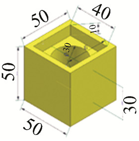
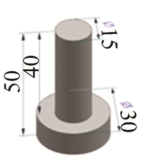
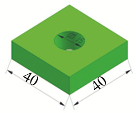
The assembly of the industrial robot pin-hole assembly workstation, as illustrated in Fig. 5, is executed using the ER3A-C60 robot, gripper, four assembly components, and a worktable. Each assembly component undergoes two pin-hole assemblies, commencing with the assembly of part 2 onto part 1, followed by the assembly of part 3 onto part 2. To simulate the virtual assembly, parts were meticulously designed using SolidWorks, with detailed specifications provided in Table 3. Subsequently, these virtual assembly parts underwent lightweight processing with PIXYZ before being imported into Unity3D 2021.3.31f1c1.

|
Fig.5 Physical setup for industrial robot device axial hole assembly operation |
| Table 3 Assembly components |
The results of system testing align closely with the actual operation of the industrial robot pin-hole assembly workstation, showcasing its proficiency in simulating pre-assembly functions. With the integration of physical mechanisms into the system, it has gained the ability to generate task trajectory guidance and visually represent the gripping force magnitude on the robot end effector. Fig. 6 elucidates various stages of the virtual pin-hole assembly process.

|
Fig.6 Axial hole virtual assembly operation system |
During the experiment, Table 4 meticulously documented the changes in clamping force throughout the "clamp-lift-translate-lower-release" cyclical operation. The entire cycle lasted 4 s, during which the clamping force was deliberately engineered to meet the demands of each distinct phase. Initially, within 0.1 s, the clamping force rapidly ascended to 2.0 N, effectively overcoming static friction. It then stabilized at 1.57 N for the subsequent 0.4 s, ensuring the object was securely held. As the lift phase commenced, the clamping force slightly increased to 1.7 N over a 1 s duration to counteract the object's sag due to gravity. This was followed by a 1.5 s translation phase, where the clamping force fluctuated mildly between 1.55 and 1.60 N to accommodate dynamic shifts during translation. In the ensuing 0.5 s lowering phase, the clamping force edged up to 1.65 N in preparation for the impending placement action. Finally, during the 0.5 s release phase, the clamping force gradually decreased to 0 N, enabling the precise placement of the object and completing the cycle.
| Table 4 Clamping force data |
During the experiment, the system's user interface (UI) actively displayed the numerical changes in clamping force, which were embedded with physical attributes to visually represent the physics of the clamping force. Fig. 7 thoroughly illustrates the trends in clamping force variation predicted by the system and those obtained from actual measurements throughout the operational cycle, including a comparative analysis. The results indicate an average error value of 0.03 between the two, validating the feasibility and effectiveness of integrating physical mechanisms into the virtual assembly system. This finding solidifies the foundation for further optimizing system performance and enhancing operational precision.

|
Fig.7 Actual and system clamping forces |
4 Conclusions
A method for constructing an industrial robot assembly system utilizing virtual reality technology is presented in this paper. Through an in-depth analysis of dynamic interactions among assembly components and a synthesis of critical elements in virtual assembly operations, the incorporation of five dimensions into virtual operations is advocated in this paper: three-dimensional models, virtual scenes, knowledge systems, task quality, and physical properties. Subsequently, a virtual pin-hole assembly system is meticulously developed. However, recognizing the intricate diversity within the realm of industrial robots and analogous equipment, there arises a paramount necessity for a profound integration of physical mechanisms with virtual systems. This integration is pivotal for augmenting the realism of system simulations. Future research endeavors should focus on conducting a more comprehensive analysis of the intrinsic mechanisms embedded in industrial equipment. Moreover, researchers should seamlessly integrate these mechanisms into virtual systems, with the ultimate goal of achieving precise and realistic simulation effects. This concerted effort is poised to significantly enhance the applicability and operability of virtual assembly systems in real-world industrial production.
AcknowledgementsWe would like to express our gratitude to the senior students of Anhui Polytechnic University for their preliminary research on virtual reality technology. We also appreciate the technical support provided by the researchers at Wuhu Anpu Robot Industry Technology Research Institute. Special thanks to Professor Xu Dezhang for his contributions to the revision, refinement, and improvement of the experimental design in this paper.
| [1] |
Deepak B B V L, Bala Murali G, Raju Bahubalendruni M V A, et al. Assembly sequence planning using soft computing methods: A review. Proceedings of the Institution of Mechanical Engineers, Part E: Journal of Process Mechanical Engineering, 2019, 233(3): 653-683. DOI:10.1177/0954408918764459 (  0) 0) |
| [2] |
Kalpakjian S, Schmid S R. Manufacturing Engineering and Technology. London: Prentice Hall, 2009, 568-571. ( 0) |
| [3] |
Whitney D E. Mechanical Assemblies: Their Design, Manufacture, and Role in Product Development. New York: Oxford University Press, 2004.
( 0) |
| [4] |
Bahubalendruni M V A R, Biswal B B. A review on assembly sequence generation and its automation. Proceedings of the Institution of Mechanical Engineers, Part C: Journal of Mechanical Engineering Science, 2016, 230(5): 824-838. DOI:10.1177/09544062155846 ( 0) |
| [5] |
Choi S S, Jung K, Do Noh S. Virtual reality applications in manufacturing industries: Past research, present findings, and future directions. Concurrent Engineering, 2015, 23(1): 40-63. DOI:10.1177/1063293X14568814 ( 0) |
| [6] |
Li Junrong. Analysis of installation technology for mechanical engineering automation equipment. China Equipment Engineering, 2023(10): 220-222. ( 0) |
| [7] |
Wang Y, Liu W. Research on the application of virtual simulation technology in industrial robot motor assembly. Electrical Drive Automation, 2023, 45(2): 42-45. ( 0) |
| [8] |
Choi A C K, Chan D S K, Yuen A M F. Application of virtual assembly tools for improving product design. The International Journal of Advanced Manufacturing Technology, 2002, 19: 377-383. DOI:10.1007/s001700200027 ( 0) |
| [9] |
Yang X S. Research on engine virtual disassembly system based on unity3D. Machinery, 2016, 43(1): 32-35, 73. ( 0) |
| [10] |
Xiong Z. Development of VR teaching system for engine dis-assembly. arXiv preprint. 2022, abs/2207.05265. DOI: 10.48550/arXiv.2207.05265.
( 0) |
| [11] |
Feng Guizhen, Chi Jianbin, Xing Haijun, et al. Virtual disassembly experiment of gearbox based on Unity3D. Journal of Graphics, 2018, 39(2): 304-308. ( 0) |
| [12] |
Feng Guizhen, Chi Jianbin, Wang Daming, et al. Construction of Gearbox Virtual Disassembly Experiment System. Journal of Engineering Graphics, 2011, 32(1): 89-93. ( 0) |
| [13] |
Li Yadong. Design of modular virtual teaching system for robotic watch based on Unity3D. Automation Application, 2020(8): 156-159. DOI:10.19769/j.zdhy.2020.08.059 ( 0) |
| [14] |
Gao Wei. Research on Virtual Assembly Technology Based on Physical Properties. Xi'an: Xidian University, 2015. DOI: 10.7666/d.D01350162.
( 0) |
| [15] |
Wilhelms J. Using dynamic analysis for realistic animation of articulated bodies. IEEE Computer Graphics and Applications, 1987, 7(6): 12-27. DOI:10.1109/MCG.1987.276893 ( 0) |
| [16] |
Liu K, Yin X, Fan X, et al. Virtual assembly with physical information: a review. Assembly Automation, 2015, 35(3): 206-220. DOI:10.1108/AA-09-2014-074 ( 0) |
| [17] |
Jayaram S, Connacher H I, Lyons K W. Virtual assembly using virtual reality techniques. Computer-Aided Design, 1997, 29(8): 575-584. DOI:10.1016/s0010-4485(96)00094-2 ( 0) |
| [18] |
Jayaram S, Jayaram U, Wang Y, et al. VADE: A virtual assembly design environment. IEEE Computer Graphics and Applications, 1999, 19(6): 44-50. DOI:10.1109/38.799739 ( 0) |
| [19] |
Tecchia F, Carrozzino M, Bacinelli S, et al. A flexible framework for wide-spectrum VR development. Presence: Virtual and Augmented Reali, 2010, 19(4): 302-312. DOI:10.1162/pres_a_00002 ( 0) |
| [20] |
Steinicke F, Ropinski T, Hinrichs K. A generic virtual reality software system's architecture and application. Proceedings of the 2005 International Conference on Augmented Tele-existence. New York: ACM, 2005: 220-227. DOI: 10.1145/1152399.1152440.
( 0) |
| [21] |
Astheimer P, Felger W, Müller S. Virtual design: A generic VR system for industrial applications. Computers & Graphics, 1993, 17(6): 671-677. DOI:10.1016/0097-8493(93)90116-q ( 0) |