2. 四川大学 空天科学与工程学院,成都 610065
2. School of Aeronautics and Astronautics, Sichuan University, Chengdu 610065, China
钛合金因其比强度高、耐腐蚀等优点而被广泛应用于新一代飞机[1-2]。铆接是飞机钛合金构件最主要的连接方式之一,但钛合金属于典型的难成形材料[3],冷铆十分困难。实践和研究表明,电磁铆接是实现飞机钛合金铆钉铆接的有效手段[4-5]。
电磁铆接利用高加载速率、一次成形的特点,通过绝热剪切变形的形式实现钛合金铆钉铆接成形[6-7],且在欠阻尼状态下铆接效果最好[8]。Deng等人[7]发现电磁铆接电压越高,镦头绝热剪切带越明显。Zhang等人[9]进一步通过数值模拟发现钛合金铆钉铆接成形过程中温度可高达426 ℃,且铆钉与层板形成了较高的干涉量。此外,有效的干涉量可以显著提高机械连接构件疲劳寿命[10-12],电磁铆接干涉量较普通铆接更均匀[13],甚至可实现复合材料无损铆接[14],电磁铆接构件疲劳寿命更高[15]。然而,生产实践中,难免会对已铆接部位进行铆钉拆卸(如维修),但拆卸后的部位铆接孔径明显变大,导致再次铆接时传统铆接方法全都无法形成有效干涉甚至无法铆接。电磁铆接能否实现此类大间隙量钛合金铆钉铆接并形成有效干涉量尚不清楚[16],不利于我国飞机钛合金构件的有效应用。
因此,本文针对飞机维修中大间隙量钛合金铆钉铆接问题,通过试验,研究钛合金铆钉的电磁铆接极限间隙量,并评估不同间隙下的铆接构件拉剪性能,为我国飞机钛合金铆接构件维修提供指导。
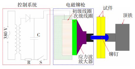
1 试验设计电磁铆接基本铆接原理如图 1所示:通过电容对初级线圈放电,初级线圈在次级线圈上感生涡流,初级和次级线圈的磁场相互作用激发脉冲电磁力,脉冲电磁力进而作用于铆钉实现铆钉镦头成形。电磁铆接通过高应变率一次成形的方式实现钛合金铆钉的铆接。
|
图 1 钛合金构件电磁铆接原理 Fig.1 Principle of electromagnetic riveting of Ti alloy parts |
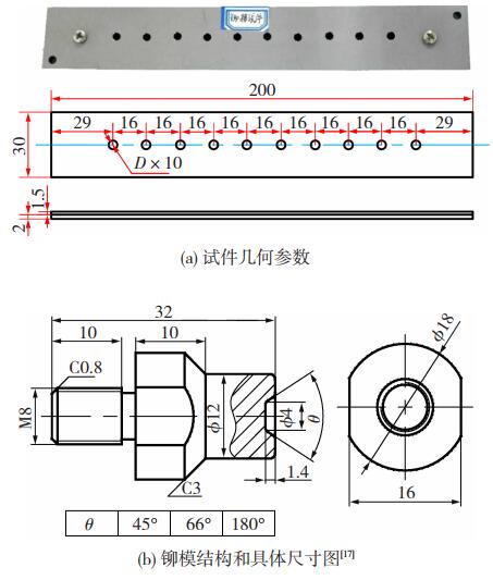
铆接试件如图 2(a)所示:试件为长200 mm,宽30 mm的双层板,根据我国某机型的实际维修情况,层板厚度分别为2 mm和1.5 mm,层板材料均为TC4;根据工程实际,铆钉选择直径为4 mm的TB2钛合金铆钉,外伸量h=4.5 mm[7],其20 ℃时的力学性能曲线如图 3所示[7];每个试件上10个孔,为了避免边距效应,孔间间距为4倍的铆钉直径即16 mm;为了研究不同间隙下的铆接质量,分别选择4.1、4.2、4.3和4.5 mm 4种钉孔直径,同时,为了避免偶然误差,每组钉孔进行4次铆接试验。铆接实验所选的模具具体尺寸如图 2(b)[17]所示。
|
图 2 铆接试件及电磁铆接设备(单位: mm) Fig.2 Riveting specimens and electromagnetic riveting equipment: (a) geometric parameters of the specimen; (b) riveting mold and its dimension[17] |
电磁铆接实验设备如图 4所示,利用西北工业大学生产的EMR1000半自动电磁铆接设备进行铆接,铆接过程中试件两端用螺栓固定在铆接型架上,铆接电压700 V。铆枪线圈具体信息如表 1所示。铆钉成形主要在脉冲电流的第一个半波内完成:
| ${t_0} = \frac{{{T_0}}}{2} $ | (1) |

|
图 4 EMR1000半自动化电磁铆接设备 Fig.4 EMR1000 semi-automatic electromagnetic riveting equipment |
| 表 1 线圈具体参数 Table 1 Coil parameters |
T0为放电电流周期,与回路电感L和电容C相关:
| ${T_0} = 2\pi \sqrt {LC} $ | (2) |
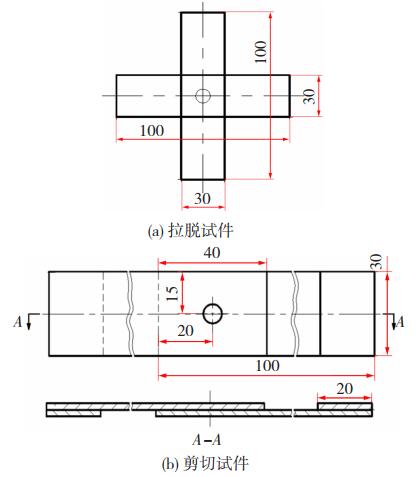
为了进一步评估不同间隙量下电磁铆接的铆接效果,设计了相应的钛合金铆接构件拉剪试验。拉剪试验选择与铆接试验完全相同的铆钉和层板,其中:拉脱试验采用单钉单拉脱试件,试件几何参数详见图 5(a);剪切试验采用单钉单搭接试件,试件几何参数详见图 5(b)[18-19]。
|
图 5 拉剪试件几何参数(单位:mm) Fig.5 Dimension of the tensile shear specimen: (a) tensile specimen; (b) shear specimen |
拉剪试验均在长春材料试验机研究所生产的CSS-44100材料试验机上进行,如图 6所示。试验过程中,采用摩擦夹紧型夹具。夹持试样的夹具为自准直夹头,此夹头能使载荷中心沿试样贴合面通过铆钉中心线,偏差不大于0.125 mm。

|
图 6 钛合金铆接构件拉剪性能测试实物图 Fig.6 Photo of tensile and shear equipment of titanium alloy riveting parts |
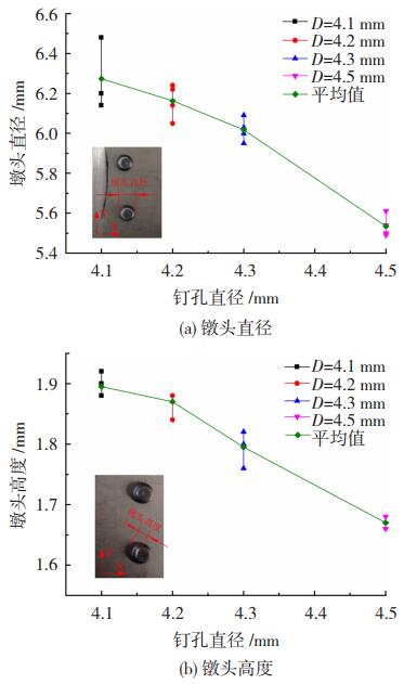
图 7为钉孔直径与镦头直径及高度的关系。
|
图 7 钉孔直径对钛合金铆钉镦头直径及高度的影响 Fig.7 Influence of hole diameter on the upsetting head diameter and height of titanium alloy riveting: (a) heading diameter; (b) heading height |
从图 7(a)可以看出,随着钉孔直径的增加,镦头直径减小;从图 7(b)可以看出,随着钉孔直径的增加,镦头高度降低,这个结果与预期一致。铆接的过程是在外力作用下,使铆钉产生塑性变形的过程。在铆接过程中铆钉钉杆会镦粗并填满钉孔,而钉孔外剩余的材料会在铆模的约束下形成钉头。在这个过程中,铆钉的体积是恒定的,而随着钉孔的扩大,填满钉孔的材料会增多,剩余的材料会相应减少,因此其形成的镦头的直径和高度也会随之相应的减小。
2.1.2 镦头绝热剪切图 8为铆接后对试件进行切割抛光处理之后的钉头剖面及镦头绝热剪切带分布图。从图中可以看出,铆接后的试件,钉杆膨胀均匀,这有利于钉杆完全填充钉孔,使钉杆与钉孔产生良好的干涉。镦头底部和钉头的底部都与铆接材料的表面结合紧密。铆接试件钉孔拐角处也能与铆钉有效结合。

|
图 8 钛合金铆钉镦头绝热剪切带分布 Fig.8 Distribution of adiabatic shear band on titanium alloy rivet heading |
在其剖面图上还可以很清晰的观察到绝热剪切带。绝热剪切带是铆钉在高应变速率下钉杆材料为了适应大变形而在钉杆的内部产生了材料之间的滑移。绝热剪切带基本上都是介于镦头顶部与底部之间,形成两个对角线交叉的形状。在金相组织图片中可以明显的观察到,在绝热剪切带上,有材料流动的痕迹,这是材料在滑移过程中产生的,而在绝热剪切带之外,材料组织没有变化。这表明,在镦头的形成过程中,材料的变形主要是集中在绝热剪切带区域。
2.1.3 钉杆干涉量铆接试验完成后,对试件进行干涉量测量。其相对干涉量公式:
| $\Delta = \frac{{d - D}}{D} \times 100\% $ | (3) |
式中d和D分别为成形后铆钉直径和成形前夹层孔径。
为了较全面反映干涉量的情况,选择3个测量点位,分别是距离镦头孔口0.5 mm处、距离钉头孔口0.5 mm和铆钉连接段的中间位置,测试结果如图 9所示。3个位置测量结果表现出一致的特征,即干涉量随着钉孔直径的增加而降低,如图 9(a)和(b)所示。

|
图 9 钉孔直径对钛合金铆钉铆接干涉量的影响 Fig.9 Influence of nail hole diameter on interference of titanium alloy riveting: (a) measuring position 1;(b) measuring position 2;(c) measuring position 3;(d) diameter of nail rods after expansion at each measure position |
其中,当钉孔直径达到4.5 mm时,其测量点二和测量点三均出现了负数,这说明当钉孔直径达到4.5 mm时,钉孔与钉杆并不能形成有效的干涉。干涉量的下降对于铆钉的疲劳寿命有着不利的影响,因此,对于4 mm的钛合金铆钉,钉孔的直径应控制在4.5 mm以内。
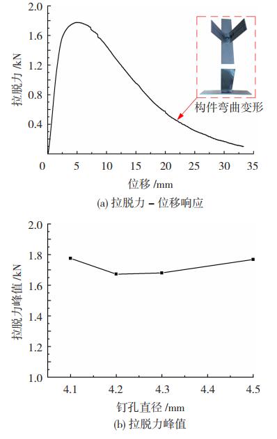
2.2 拉剪性能分析 2.2.1 拉脱性能图 10为钛合金铆接构件的拉脱性能。图 10(a)为典型的拉脱实验曲线,由于试件的抗弯强度不够,所以所有试件的拉脱实验结果都发生了弯曲变形,铆接在一起的两个板并没有完全分开。根据实验结果,我们得到了不同钉孔直径下的拉脱力峰值,如图 10(b)。从图中可以看出,拉脱力峰值相差不大,且没有表现出明显的变化趋势。
|
图 10 钛合金铆接构件拉脱性能 Fig.10 Pulling out strength properties of titanium alloy riveting parts: (a) pulling out strength-displacement response; (b) peak pulling out strength |
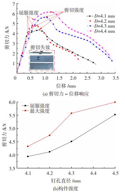
图 11为钛合金铆接构件剪切性能。
|
图 11 钛合金铆接构件剪切性能 Fig.11 Shear properties of titanium alloy riveting parts: (a) shear force-displacement response; (b) shear force strength |
从图 11(a)可以看出,不同孔径的剪切实验曲线均表现出相似的轮廓特征。首先在弹性变形阶段,曲线的上升斜率基本相似。随着剪切力的增加,试件发生屈服进入塑性变形阶段。随着剪切力的继续增加,达到了试件的最大屈服强度。随后剪切力明显降低,试件已经失效。钛合金铆接构件的屈服强度和剪切强度与钉孔直径的关系如图 11(b)所示,从图中可以看出,试件的屈服强度和剪切强度均随着钉孔直径的增加而增加。所以从提高剪切强度的角度考虑,钉孔直径的增加有利于提高抗剪切能力。
3 结论1) 实验表明电磁铆接通过绝热剪切的形式可以对钛合金铆钉实现大的塑性变形,能够顺利形成镦头。电磁铆接也可以有效实现大钉孔间隙下TC4钛合金构件铆接,钉孔间隙量≤0.3 mm时均能形成明显的干涉配合。
2) 随着钉孔间隙的增加,电磁铆接过程中更多钉杆材料进入钉孔内,镦头直径和高度均发生明显的减少。
3) 电磁铆接干涉量随钉孔间隙增加而显著降低,但钉杆膨胀后直径呈现出线性增加。
4) 本试验条件下,铆接构件拉脱失效模式均为试件弯曲,拉脱性能对钉孔间隙量不敏感; 剪切失效模式均为剪切失效,剪切屈服强度和剪切最大强度均随钉孔干涉量的增加而增加。
| [1] |
董瑞峰, 李金山, 唐斌, 等. 航空紧固件用钛合金材料发展现状[J]. 航空制造技术, 2018, 61(4): 86-91. Dong Ruifeng, LI Jinshan, TANG Bin, et al. Development status of titanium alloy materials for aerospace fasteners[J]. Aerospace Manufacturing Technology, 2018, 61(4): 86-91. DOI:10.16080/j.issn1671-833x.2018.04.086 |
| [2] |
付艳艳, 宋月清, 惠松骁, 等. 航空用钛合金的研究与应用进展[J]. 稀有金属, 2007, 30(6): 850-856. Fu Y Y, SONG Y Q, Hui S X, et al. Research and application progress of titanium alloy for aviation[J]. Rare Metals, 2007, 30(6): 850-856. DOI:10.13373/j.cnki.cjrm.2006.06.028 |
| [3] |
丁文锋, 奚欣欣, 占京华, 徐九华, 傅玉灿, 苏宏华. 航空发动机钛材料磨削技术研究现状及展望[J]. 航空学报, 2019, 40(6): 022763. DING Wenfeng, XI Xinxin, ZHAN Jinghua, , , , et al. DING Wenfeng, XI Xinxin, ZHAN Jinghua, et al. Research status and future development of grinding technology of titanium materials for aero-engines[J]. Acta Aeronauticaet Astronautica Sinica, 2019, 40(6): 022763D. DOI:10.7527/S1000-6893.2019.22763 |
| [4] |
DENG J H, YU H P, LI C F. Numerical and experimental investigation of electromagnetic riveting[J]. Materials Science Engineering A, 2009, 499(1-2): 242-247. DOI:10.1016/j.msea.2008.05.049 |
| [5] |
CAO Zengqiang, ZUO Yangjie. Electromagnetic riveting technique and its applications[J]. Chinese Journal of Aeronautics, 2020, 33(1): 5-15. DOI:10.1016/j.cja.2018.12.023 |
| [6] |
张岐良, 曹增强, 秦龙刚, 等. 钛合金电磁铆接数值模拟[J]. 稀有金属材料与工程, 2013, 42(9): 76-81. Zhang Q L, Cao Z C, QIN L G, et al. Numerical Simulation of electromagnetic riveting of titanium alloy[J]. Rare Metal Materials and Engineering, 2013, 42(9): 76-81. |
| [7] |
DENG J H, TANG C, FU M W, et al. Effect of discharge voltage on the deformation of Ti Grade 1 rivet in electromagnetic riveting[J]. Materials Science and Engineering A, 2014, 591: 26-32. DOI:10.1016/j.msea.2013.10.084 |
| [8] |
赵志衡, 江洪伟, 邓将华, 等. 低压电磁铆接固有参数对铆接性能的影响[J]. 材料科学与工艺, 2009, 17(2): 244-246. Zhao Zhiheng, JIANG Hongwei, DENG Zhenhua, et al. Influence of inherent parameters of low-voltage electromagnetic riveting on riveting performance[J]. Materials Science and Technology, 2009, 17(2): 244-246. |
| [9] |
ZHANG X, ZHANG M, SUN L, et al. Numerical simulation and experimental investigations on TA1 titanium alloy rivet in electromagnetic riveting[J]. Archives of Civil & Mechanical Engineering, 2018, 18(3): 887-901. DOI:10.1016/j.acme.2018.01.003 |
| [10] |
WEI Jingchao, JIAO Guiqiong, JIA Purong, et al. The effect of interference fit size on the fatigue Life of bolted joints in composite laminates[J]. Composites Part B: Engineering, 2013, 53: 62-68. DOI:10.1016/j.compositesb.2013.04.048 |
| [11] |
CAOYuejie, ZENG Qiang, et al. Numerical and experimental investigation of fitting tolerance effects on damage and failure of CFRP/Ti double-lap single-bolt joints[J]. Aerospace Science and Technology, 2018, 78: 461-470. DOI:10.1016/j.ast.2018.04.042 |
| [12] |
曹增强, 杨晓娜, 左杨杰, 等. 钛合金干涉螺栓应力波安装质量模拟研究[J]. 材料科学与工艺, 2018, 26(1): 30-36. Cao Z Q, Yang X A, ZUO Y J, et al. Simulation study on stress wave installation quality of titanium alloy interference bolts[J]. Materials Science and Technology, 2018, 26(1): 30-36. DOI:10.11951/j.issn.1005-0299.20170157 |
| [13] |
YOON T H, KIM S J. Refined Numerical Simulation of Three-Dimensional Riveting in Laminated Composites[J]. Journal of Aircraft, 2011, 48(4): 1434-1443. DOI:10.2514/1.C031311 |
| [14] |
JIANG H, LUO T, LI G, et al. Fatigue life assessment of electromagnetic riveted carbon fiber reinforce plastic/aluminum alloy lap joints using Weibulldistribution[J]. International Journal of Fatigue, 2017, 105(12): 180-189. DOI:10.1016/j.ijfatigue.2017.08.026 |
| [15] |
陈允全, 曹增强, 秦龙刚, 等. 钛合金结构干涉配合铆接疲劳试验研究[J]. 航空制造技术, 2017, 60(4): 83-86. Chen Y Q, CAO Z C, QIN L G, et al. Study on interference fit riveting fatigue test of titanium alloy structure[J]. Aviation Manufacturing Technology, 2017, 60(4): 83-86. DOI:10.16080/j.issn1671-833x.2017.04.083 |
| [16] |
MA X Y, GONG S L, ZHANG J X, et al. Formation, microstructure and mechanical properties of double-sided laser beam welded Ti-6Al-4V T-joint[J]. Transactions of Nonferrous Metals Society of China, 2016, 26(3): 729-735. DOI:10.1016/s1003-6326(16)64163-8 |
| [17] |
李奕寰, 曹增强, 张岐良, 等. 铆模倾角对铆接质量的影响研究[J]. 航空学报, 2013, 34(2): 426-433. Li Y H, Cao Z C, ZHANG Q L, et al. Study on the influence of riveting die Angle on riveting quality[J]. Acta Aeronauticasinica, 2013, 34(2): 426-433. DOI:10.7527/S1000-6893.2013.0049 |
| [18] |
SQUILLACE A, PRISCO U, CILIBERTO S, et al. Effect of welding parameters on morphology and mechanical properties of Ti-6Al-4V laser beam welded butt joints[J]. Journal of Materials Processing Technology, 2012, 212(2): 427-436. DOI:10.1016/j.jmatprotec.2011.10.005 |
| [19] |
ZUO Y, CAO Z, CAO Y, et al. Dynamic behavior of CFRP/Ti single-lap pinned joints under longitudinal electromagnetic dynamic loading[J]. Composite Structures, 2018, 184: 362-371. DOI:10.1016/j.compstruct.2017.09.079 |
 2021, Vol. 29


