重复使用运载器(reusable launch vehicle, RLV)的整个再入过程可分为3个阶段:大气层再入段、末端能量管理段(terminal area energy management, TAEM)与自动着陆段.末端能量管理阶段至关重要,因为它将再入段结束时处于随机状态下的RLV引导至自动着陆段的接口处(auto landing interface,ALI),并要求满足ALI处的状态约束[1-2].航天飞机TAEM段通过将RLV与航向校准柱(heading alignment cone, HAC)相切并校准航向,之后沿着跑道中心线平飞直到到达ALI处[2].尽管航天飞机的TAEM制导策略经验证有效,但是它依赖于事先离线计算的并储存好的若干参考轨迹,在初始条件扰动较大时缺乏鲁棒性[3-4].
近年来,国内外学者的研究方向致力于在线生成参考轨迹.Kluever等[5-7]为TAEM段设计了一种轨迹生成算法,利用嵌套迭代循环生成3个与航向校准柱相关的轨迹设计参数;Costa[8]和Baek等[9]将TAEM段轨迹生成问题转化为轨迹优化问题,利用非线性规划概念求解出轨迹优化问题的可行解;Hull等[10]为X-37的TAEM段和A&L段设计了一种轨迹生成算法,将轨迹生成问题转换为最优控制问题,通过求解最优控制问题得到合适的轨迹参数来修正控制指令;周敏等[11]以航向调整段进入点飞行器航向角偏差最小为目标函数,求解以动压、过载和速度滚转角限制为约束的非线性规划问题;王鹏等[12]首先将轨迹规划转化为优化问题,然后给出能量走廊之内的能量剖面跟踪策略.然而在目前众多的方法中,最优控制问题和非线性规划问题的求解非常复杂,必须采用现成的工具箱才有可能求解成功.而在实际工程实现时,将这些工具箱移植到机载计算机中会面临较大的障碍.此外,对最优控制问题和非线性规划问题求解时对初值的选择非常敏感,选择不同的初值会严重影响求解时间,甚至于初值选择不好时,会造成求解失败,而初值的选择往往只能多次试凑.
以易于工程实现为目标,本文提出了一种基于迭代校正技术的轨迹生成方法,可以根据不同的初始状态,快速生成可行的TAEM轨迹,成功到达A&L段并满足ALI处的终端约束.该算法最终仅使用了Heun数值积分、两个未知数的非线性方程组的求解、以及迭代校正技术,这些数值计算方法均非常成熟与稳定,而且不依赖于任何工具箱,非常易于机载计算机平台的实现.最后选取大量对TAEM段初始位置与航向进行大范围的散布的例子,验证该算法的快速性、有效性与鲁棒性.
1 运动方程的建立在对RLV进行末端能量管理段进行轨迹设计时,将总攻角α与倾侧角υ作为控制变量,取侧滑角为零.假使地球为平面模型,得到其三自由度质点运动方程为[13]
| $ \left\{ \begin{array}{l} \dot v = - \frac{{{C_{\rm{D}}}qS}}{m} - g\sin \theta ,\\ \dot \theta = \frac{{{C_{\rm{L}}}qS\cos \upsilon }}{{mv}} - \frac{{g\cos \theta }}{v},\\ \dot \sigma = \frac{{{C_{\rm{L}}}qS\sin \upsilon }}{{mv\cos \theta }},\\ \dot h = v\sin \theta ,\\ \dot x = v\cos \theta \cos \sigma ,\\ \dot y = v\cos \theta \sin \sigma . \end{array} \right. $ | (1) |
式中:m、v分别为RLV的质量与速度;θ、σ分别为航迹倾角与航迹方位角;h为高度;x、y分别为位置;q为动压, 表达式为q=1/2ρv2,其中ρ=ρ0e-βh;重力加速度g表示为g=g0Re2/(h+Re)2;CD、CL分别表示阻力系数与升力系数,通过对X-33的气动数据进行拟合得到[14]:
| $ \begin{array}{l} {C_{\rm{L}}}\left( {\alpha ,M} \right) = - 0.000\;522\;5{\alpha ^2} + 0.035\;06\alpha - 0.048\;57M + \\ \;\;\;\;\;\;\;\;\;\;\;\;\;\;\;\;\;0.157\;7, \end{array} $ |
| $ \begin{array}{l} {C_{\rm{D}}}\left( {\alpha ,M} \right) = 0.000\;143\;2{\alpha ^2} + 0.005\;58\alpha - 0.010\;48M + \\ \;\;\;\;\;\;\;\;\;\;\;\;\;\;\;\;\;0.220\;4, \end{array} $ |
式中,M=v/vsound为马赫数.
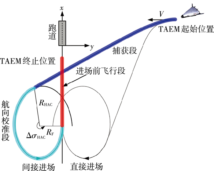
2 轨迹规划算法本文借鉴航天飞机在TAEM阶段的制导策略,将TAEM段的地面轨迹分为捕获段、航向校准段、以及进场前飞行段[15],如图 1所示.
|
图 1 航天飞机TAEM段的地面轨迹 Figure 1 Shuttle TAEM ground track |
在航向校准段,RLV沿着内旋的螺旋线进行航向修正,航向校准柱的半径定义为
| $ {R_{{\rm{HAC}}}} = {R_{\rm{F}}} + {R_2}\Delta \sigma _{{\rm{HAC}}}^2. $ |
式中:RF为最终的HAC半径;R2为二次螺旋系数;ΔσHAC为剩余的HAC螺旋校正角度.图 1同样展示了两种返回进场方式:直接进场与间接进场.
2.1 侧向制导策略捕获段位于TAEM的起始段,倾侧角指令与航迹偏差角成正比,如
| $ \upsilon = {K_{\rm{v}}}\Delta {\sigma _{{\rm{AT}}}}. $ |
式中:ΔσAT为当前与HAC相切所需的航迹方位角偏差,Kv为比例系数.
RLV在沿着HAC柱飞行的航向校准段,需满足的关系式为
| $ g\tan \upsilon = \frac{{{v^2}}}{{{R_{{\rm{HAC}}}}/\cos \theta }}. $ |
故参考倾侧角为υref=tan-1(v2cos θ/gRHAC).倾侧角的指令设为参考倾侧角的前馈项与反馈项之和:
| $ \upsilon = {\tan ^{ - 1}}\left( {\frac{{{v^2}\cos \theta }}{{g{R_{{\rm{HAC}}}}}}} \right) + {K_{\rm{R}}}\Delta R + {K_{{\rm{RD}}}}\Delta \dot R. $ |
式中:ΔR为实际与要求的HAC半径RHAC之差; KR、KRD分别为比例系数.
当RLV相对于跑道的航迹方位角小于5°时,RLV进入进场前飞行段,倾侧角指令切换为
| $ \upsilon = - {K_y}y - {K_{yD}}\dot y, $ |
式中y表示与跑道中心的横向偏差.在整个RLV的TAEM飞行段,倾侧角指令均需满足:
| $ \upsilon \le {\upsilon _{\max }}. $ |
在TAEM飞行阶段,将飞行高度代替时间作为自变量,选取跟踪动压-高度剖面.这里用一个三次多项式来定义需要跟踪的动压-高度剖面:
| $ {{\bar q}_{{\rm{ref}}}}\left( h \right) = {Q_0} + {Q_1}h + {Q_2}{h^2} + {Q_3}{h^3}. $ |
式中:Q0、Q1、Q2、Q3分别为多项式4个的系数,可由以下4个条件确定.TAEM起始点的高度h0与动压q0;ALI处的高度hALI与动压qALI;TAEM段中点处的高度hmid与此处的动压qmid,本文选取qmid=(q0+qALI)/2.ALI处的动压相对高度的变化率为0,即
| $ \frac{{{\rm{d}}{{\bar q}_{{\rm{ref}}}}\left( {{h_{{\rm{ALI}}}}} \right)}}{{{\rm{d}}h}} = {Q_1} + 2{Q_2}{h_{{\rm{ALI}}}} + 3{Q_3}h_{{\rm{ALI}}}^2 = 0, $ |
由以上4个条件可得
| $ \left\{ \begin{array}{l} {{\bar q}_0} = {Q_0} + {Q_1}{h_0} + {Q_2}h_0^2 + {Q_3}h_0^3,\\ {{\bar q}_{{\rm{ALI}}}} = {Q_0} + {Q_1}{h_{{\rm{ALI}}}} + {Q_2}h_{{\rm{ALI}}}^2 + {Q_3}h_{{\rm{ALI}}}^3,\\ {{\bar q}_{{\rm{mid}}}} = {Q_0} + {Q_1}{h_{{\rm{mid}}}} + {Q_2}h_{{\rm{mid}}}^2 + {Q_3}h_{{\rm{mid}}}^3,\\ {Q_1} + 2{Q_2}{h_{{\rm{ALI}}}} + 3{Q_3}h_{{\rm{ALI}}}^2 = 0. \end{array} \right. $ |
根据上式可求解出4个系数.参考动压-高度剖面确定以后,需确定跟踪此剖面需要的输入指令α.
利用链式法则,计算动压相对于高度的导数为
| $ \begin{array}{l} \frac{{{\rm{d}}\bar q}}{{{\rm{d}}h}} = \frac{{{\rm{d}}\bar q}}{{{\rm{d}}t}}\frac{{{\rm{d}}t}}{{{\rm{d}}h}} = \frac{{\rm{d}}}{{{\rm{d}}t}}\left( {\frac{1}{2}\rho {v^2}} \right)\frac{{{\rm{d}}t}}{{{\rm{d}}h}} = \\ \;\;\;\;\;\;\;\;\;\left( {\frac{1}{2}\frac{{{\rm{d}}\rho }}{{{\rm{d}}h}}\frac{{{\rm{d}}h}}{{{\rm{d}}t}}{v^2} + \rho v\frac{{{\rm{d}}v}}{{{\rm{d}}t}}} \right)\frac{{{\rm{d}}t}}{{{\rm{d}}h}}, \end{array} $ | (2) |
而
| $ \frac{{{\rm{d}}\rho }}{{{\rm{d}}h}} = - \beta {\rho _0}{{\rm{e}}^{ - \beta h}} = - \beta \rho . $ | (3) |
将式(3)与式(1)的第1式与第4式带入到式(2)中可得
| $ \frac{{{\rm{d}}\bar q}}{{{\rm{d}}h}} = - \bar q\beta - \frac{{\rho \bar qS{C_{\rm{D}}}}}{{m\sin \theta }} - \rho g. $ | (4) |
由式(1)中的第4式可得
| $ v = \dot h/\sin \theta , $ | (5) |
将式(5)代入式(1)中的第2式可得到
| $ \dot \theta = \frac{{\rho \dot h}}{{2\sin \theta }}\left( {\frac{{{C_{\rm{L}}}S\cos \upsilon }}{m} - \frac{{g\cos \theta }}{{\bar q}}} \right), $ |
将自变量由时间改为高度,可得
| $ \frac{{{\rm{d}}\theta }}{{{\rm{d}}h}} = \frac{\rho }{{2\sin \theta }}\left( {\frac{{{C_{\rm{L}}}S\cos \upsilon }}{m} - \frac{{g\cos \theta }}{{\bar q}}} \right), $ | (6) |
将式(6)与式(4)联立,可得
| $ \left\{ \begin{array}{l} \frac{{{\rm{d}}\theta }}{{{\rm{d}}h}} = \frac{\rho }{{2\sin \theta }}\left( {\frac{{{C_{\rm{L}}}S\cos \upsilon }}{m} - \frac{{g\cos \theta }}{{\bar q}}} \right),\\ \frac{{{\rm{d}}\bar q}}{{{\rm{d}}h}} = - \bar q\beta - \frac{{\rho \bar qS{C_{\rm{D}}}}}{{m\sin \theta }} - \rho g = {Q_1} + 2{Q_2}h + 3{Q_3}{h^2}. \end{array} \right. $ | (7) |
通过求解非线性方程(7)可以得到跟踪动压-高度剖面所需的控制变量α与状态变量θ.
2.3 轨迹生成策略RLV的各状态变量相对于高度的微分方程:
| $ \left\{ \begin{array}{l} \frac{{{\rm{d}}\upsilon }}{{{\rm{d}}h}} = - \frac{{{C_{\rm{D}}}qS}}{{mv\sin \theta }} - \frac{g}{v},\\ \frac{{{\rm{d}}\theta }}{{{\rm{d}}h}} = \frac{{{C_{\rm{L}}}qS\cos \upsilon }}{{m{v^2}\sin \theta }} - \frac{{g\cos \theta }}{{{v^2}\sin \theta }},\\ \frac{{{\rm{d}}\sigma }}{{{\rm{d}}h}} = \frac{{{C_{\rm{L}}}qS\sin \upsilon }}{{m{v^2}\sin \theta \cos \theta }},\\ \frac{{{\rm{d}}x}}{{{\rm{d}}h}} = \frac{{\cos \theta \cos \sigma }}{{\sin \theta }},\\ \frac{{{\rm{d}}y}}{{{\rm{d}}h}} = \frac{{\cos \theta \sin \sigma }}{{\sin \theta }}. \end{array} \right. $ |
采用Heun法,积分步长取Δh=-100 m,对微分方程从h0到hALI进行数值积分.利用横向和纵向的制导策略,可以保证除了x外,其余4个变量均可满足TAEM末端的终端约束.本文采取迭代校正算法的目的就在于通过校正侧向的地面轨迹来调整航程,使RLV到达TAEM段的末端时满足x=xALI.
2.4 迭代校正算法TAEM段轨迹生成策略的详细流程为:首先确定合适的进场方式.先测试间接进场方式可不可行.若在最短航程的间接进场模式下,RLV的最终位置xf超过了ALI的起点位置xALI,则确定为间接进场;若没有超过则测试直接进场方式.若在最短航程的直接进场模式下,RLV的最终位置xf超过了ALI处的位置xALI,则将进场方式确定为直接进场.否则,不存在可行的TAEM轨迹.
之后运行迭代校正算法,每次的迭代过程中,HAC的位置xHAC由下式调整:
| $ x_{{\rm{HAC}}}^{k + 1} = x_{{\rm{HAC}}}^k + bs_{{\rm{go}}}^k. $ | (8) |
式中:上标k为迭代次数;sgok=xALI-xf,表示TAEM段结束时RLV到ALI段起始点的距离误差;系数b为校正因子,最终的HAC半径由以下方法确定:
| $ R_{\rm{F}}^{k + 1} = R_{\rm{F}}^k - \left( {1 - b} \right)s_{{\rm{go}}}^k\left[ {\frac{{R_{\rm{F}}^k - R_{\rm{F}}^{k - 1}}}{{s_{{\rm{go}}}^k - s_{{\rm{go}}}^{k - 1}}}} \right]. $ | (9) |
根据式(8)、(9)运行迭代校正迭代算法调整HAC位置xHAC与最终的HAC半径RF,直到sgo的误差收敛于150 m的范围之内.
3 数值仿真本文对TAEM段初始位置与航迹偏角同时进行一系列散布,并进行仿真.自动着陆段接口处状态约束分别为hALI=3 000 m,vALI=150 m/s,xALI=-8 000 m,yALI=0.TAEM段初始高度、速度与航迹倾角状态变量分别为h0=20 000 m,v0=286 m/s,θ0=-10°.
仿真结果见表 1.本文的算法由Matlab 2012a编程实现,在操作系统为Windows 7 64位,CPU为Intel i3-2310的计算机上运行得到.结果显示,轨迹生成时间根据迭代次数在4~12 s之内.
| 表 1 不同的起始位置与航迹方位角情况下的仿真结果 Table 1 Simulation results for distribution of initial positions and azimuth angles |
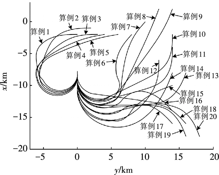
图 2为表 1中20个算例的TAEM段的地面轨迹.可以看出,本文的迭代校正迭代算法可以根据不同的初始条件自动调整HAC位置xHAC与最终的HAC半径RF,直到最终到达ALI处.
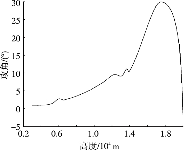
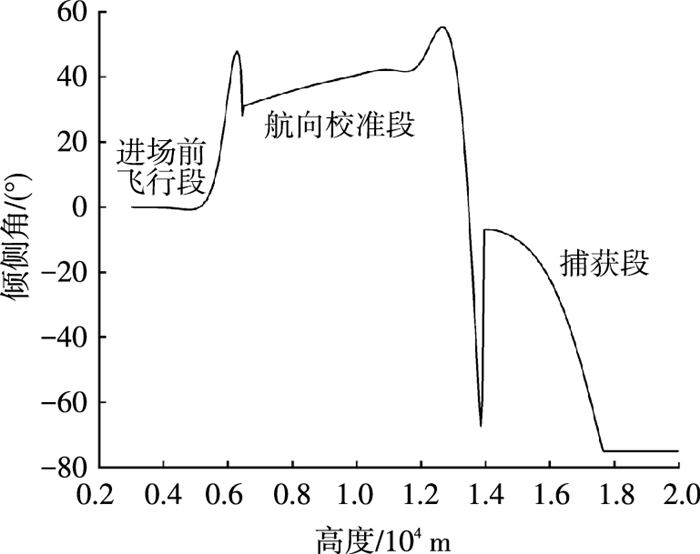
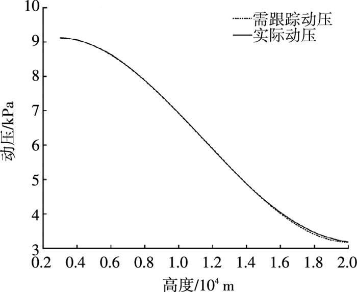
图 3、4表示在算例18中由本文算法生成的控制变量剖面图.图 5为例子18中的参考动压-高度曲线与实际动压-高度曲线的对比图,从图中可以看到在整个飞行过程中实际动压曲线在跟踪参考动压曲线时均取得了良好的跟踪效果,从而达到了控制TAEM段末端速度的目的.
|
图 3 算例18的攻角剖面图 Figure 3 Angle of attack profile for case 18 |
|
图 4 算例18的倾侧角剖面图 Figure 4 Bank angle profile for case 18 |
|
图 5 算例18的参考动压-高度剖面与实际动压-高度剖面对比图 Figure 5 Comparison of reference and actual dynamic pressure profile |
1) 本文为RLV在TAEM段提出了一种快速的在线轨迹生成算法.通过迭代校正迭代算法确定HAC的位置与最终半径,从而调整RLV的航程,使其到达末端时各个状态均满足ALI处的边界约束.
2) 仿真表明,本文给出的算法可根据RLV在TAEM初始阶段的状态,自动选择进场策略,并调整HAC的位置与最终半径,生成可行的TAEM可行轨迹.仿真结果验证了算法的快速性、有效性与鲁棒性.
3) 本文提出的方法并不依赖于事先离线计算好的轨迹,且使用的数值方法成熟且稳定,不使用任何工具箱,便于工程实现.
| [1] |
De RIDDER S, MOOIJ E. Terminal area trajectory planning using the energy-tube concept for reusable launch vehicles[J].
Acta Astronautica, 2011, 68(7/8): 915-930.
DOI: 10.1016/j.actaastro.2010.08.032 |
| [2] |
句美琪, 何英姿. 基于高度跟踪的末端能量管理段制导[J].
空间控制技术与应用, 2014, 40(4): 42-46.
JU Meiqi, HE Yingzi. Guidance terminal area energy management phase based on height profile tracking[J]. Aerospace Control and Application, 2014, 40(4): 42-46. DOI: 10.3969/j.issn.1674-1579.2014.04.008 |
| [3] |
LIANG Zixuan, LI Qingdong, REN Zhang. Onboard planning of constrained longitudinal trajectory for reusable launch vehicles in terminal area[J].
Advances in Space Research, 2016, 57(3): 742-753.
DOI: 10.1016/j.asr.2015.11.027 |
| [4] |
司马骏, 黄一敏. RLV末端能量管理段混合制导方案[J].
航天控制, 2014, 32(1): 30-34, 39.
SIMA Jun, HUANG Yimin. A mixed guidance method for terminal area energy management of RLV[J]. Aerospace Control, 2014, 32(1): 30-34, 39. DOI: 10.3969/j.issn.1006-3242.2014.01.006 |
| [5] |
KLUEVER C A, HORNEMAN K R. Terminal trajectory planning and optimization for an unpowered reusable launch vehicle[C]//AIAA Guidance, Navigation, and Control Conference and Exhibit. San Francisco, California: AIAA, 2005. DOI: 10.2514/6.2005-6058.
|
| [6] |
KLUEVERC A, NEAL D A. Approach and landing range guidance for an unpowered reusable launch vehicle[J].
Journal of Guidance, Control, and Dynamics, 2015, 38(11): 2057-2066.
DOI: 10.2514/1.g000909 |
| [7] |
HORNEMANK R, KLUEVER C A. Terminal area energy management trajectory planning for an unpowered reusable launch vehicle[C]//AIAA Atmospheric Flight Mechanics Conference and Exhibit. Providence, Rhode Island: AIAA, 2004. DOI: 10.2514/6.2004-5183.
|
| [8] |
COSTA R D. Studies for terminal area gnc of reusable launch vehicles[C]//AIAA Guidance, Navigation And Control Conference and Exhibit. Austin, Texas, AIAA, 2003. DOI: 10.2514/6.2003-5438.
|
| [9] |
BAEK J H, LEE D W, KIM J H, et al. Trajectory optimization and the control of a re-entry vehicle in TAEM phase[J].
Journal of Mechanical Science and Technology, 2008, 22(6): 1099-1110.
DOI: 10.1007/s12206-008-0501-y |
| [10] |
HULL J R, GANDHI N, SCHIERMAN J D. In-flight TAEM/final approach trajectory generation for reusable launch vehicles[C]// Infotech@ Aerospace. Arlington, Virginia:AIAA, 2005. DOI: 10.2514/6.2005-7114.
|
| [11] |
周敏, 周军, 郭建国. RLV末端能量管理段轨迹在线规划与制导[J].
宇航学报, 2015, 36(2): 151-157.
ZHOU Min, ZHOU Jun, GUO Jianguo. On-line trajectory planning and guidance for terminal area energy management of reusable launch vehicle[J]. Journal of Astronautics, 2015, 36(2): 151-157. DOI: 10.3873/j.issn.1000-1328.2015.02.004.j.issn.1000-1328.2015.02.004 |
| [12] |
王鹏, 党晓康, 马松辉. RLV末端能量管理段轨迹优化与纵向控制律设计[J].
电子设计工程, 2014, 22(20): 42-44.
WANG Peng, DANG Xiaokang, MA Songhui. Trajectory optimization and longitudinal control for terminal area energy management of reusable launch vehicle[J]. Electronic Design Engineering, 2014, 22(20): 42-44. DOI: 10.3969/j.issn.1674-6236.2014.20.012 |
| [13] |
潘彦鹏, 周军, 呼卫军. 一种基于在线能量推演的自适应末端能量管理方法[J].
西北工业大学学报, 2012, 30(5): 757-762.
PAN Yanpeng, ZHOU Jun, HU Weijun. An effective and adaptive method of terminal area energy management (TAEM) based on online energy backstepping[J]. Journal of Northwestern Polytechnical University, 2012, 30(5): 757-762. DOI: 10.3969/j.issn.1000-2758.2012.05.023 |
| [14] |
BOLLINO K P, ROSS I M, DOMAN D D. Optimal nonlinear feedback guidance for reentry vehicles[C]//AIAA Guidance, Navigation, and Control Conference. Keystone, Colorado: AIAA, 2006. DOI: 10.2514/6.2006-6074.
|
| [15] |
陈功, 解志军, 崔乃刚. 升力式再入飞行器末端能量管理方法[J].
哈尔滨工业大学学报, 2012, 44(9): 20-24.
CHEN Gong, XIE Zhijun, CUI Naigang. The method of terminal area energy management for lifting reentry vehicle[J]. Journal of Harbin Institute of Technology, 2012, 44(9): 20-24. DOI: 10.11918/j.issn.0367-6234.2012.09.003 |
 2017, Vol. 49


