2. 材料与光电研究中心(中国科学院大学),北京 100049
2. Center of Materials Science and Optoelectronics Engineering (University of Chinese Academy of Sciences), Beijing 100049, China
星载电子系统容易受到空间高能粒子、质子和中子的影响发生单粒子效应(Single Event Effect,SEE),从而产生软错误,在大规模集成电路芯片系统中,静态随机存储器(Static Random Access Memory, SRAM)约占一半以上的面积[1],系统中出现的错误绝大部分也与存储器有关.因此,对存储器单元进行加固是降低集成电路系统软错误率(Soft Error Radio,SER)的重要途径之一[2-3].
随着半导体工艺节点的不断降低,SRAM对SEE更加敏感.当集成电路尺寸降低到深亚微米(< 0.18 μm)以下时,存储器内受单粒子翻转(Single Event Upsets, SEU)的影响不会明显增加,而是逐渐趋于饱和[4].但是由于工艺节点的降低,相同面积内摆放了更多的存储单元,使得存储器发生多位翻转(Multiple Bits Upset, MBU)的概率大大增加[5-6].
为了提高SRAM单元抗SEE的能力,常用的加固方法可以分为两种,一种为工艺加固,另一种为设计加固.工艺加固主要采用SOI或者GaAs工艺[7-8],能够取得很好的抗辐射效果;设计加固主要可以分为电路级、版图级和系统级加固.电路加固通过加入反馈电路来维持存储节点电容上的电荷值来增强抗辐射效果,如双互锁存储单元(Dual Interlocked storage Cell, DICE)结构[9];版图加固通常采用版图交错技术[10],它把不同字上的位单元分配成在物理版图上相邻的单元,从而避免同一个字上的多个位单元同时发生翻转,但是这种方法会使得存储器布线增长,当交错位数变多时,上述问题会更加明显.系统级加固主要采用检错纠错(Error Detection And Correction, EDAC)技术,常用的EDAC编码有汉明码[11]、BCH码[12]和RS码[13].汉明码译码电路比较简单,但是只能纠正一位翻转或者检测出两位翻转;BCH码和RS码可以修正存储器中出现的多位翻转,但是他们的编码和译码电路比较复杂[14-15],需要以查找表的方式处理高阶域的乘法运算,具有较大的电路延迟.
因此,本文针对系统级加固提出一种双模冗余汉明(Dual Modular Redundancy Hamming,DMRH)码,它能够修正存储器中出现的一位翻转和两位翻转,且电路延迟小于两位修正能力的BCH码.
1 双模冗余汉明码的设计 1.1 纠一检二汉明码汉明码基本原则是在n位原码的基础上插入k位的校验码,校验码依据汉明码编码规则生成,记录了原码的部分信息,能够在所存储的数据中出现一位翻转时对错误进行修正[16-17],其中n与k的关系式为
| $ {2^k} \ge n + k + 1. $ | (1) |
在需要读取所存储的n+k位数据之前,依据汉明码的解码规则,生成k位状态码(记为S0~Sk-1).若所存储的数据中未发生翻转,S0~Sk-1每一位状态码的值均为0;若数据在存储过程中发生了一位错误,出错位置不同,状态码的值也将不同.因此,可以根据状态码的值确定翻转的位置,对错误进行修正.
此外,在汉明码的基础上再增加一位校验位(记为Pk)就可实现纠一检二的功能.在汉明码编码阶段,Pk生成式为将n+k位数据进行异或运算.
在需要读取所存储的n+k+1位数据之前,使用所读出来的n位原码与k+1位校验码相异或,得到k+1位的状态码(记为Sk).在纠一检二汉明码中,若Sk的值为0,同时S0~Sk-1全为0,则代表所存储数据内未发生翻转;若Sk的值为1,则代表所存储数据中出现了一位翻转;若Sk的值为0,同时S0~Sk-1不全为0,则代表数据中出现了两位翻转.
在表 1中,假设k=4,说明状态码与错误类型对照关系.表中记S0~Sk-1为St,××××为不等于0000的值.
| 表 1 状态码与错误类型对照表 Tab. 1 Contrast between status code and different error types |
在汉明码解码模块内定义信号两位翻转标志位S_2err_flag,则其生成关系式为
| $ S\_2err\_flag = \left( {{S_k} = 0\& \& {{\rm{S}}_t} \ne 4'{\rm{b}}0000} \right)?1'b1:1'b0. $ | (2) |
当数据中出现两位翻转时,S_2err_flag值为1;否则该值为0.
1.2 双模冗余汉明码的设计为了提高SRAM单元抗MBU的能力,本文在前节纠一检二汉明码的基础上,提出了一种双模冗余汉明码.DMRH码各模块说明如下:
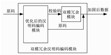
1.2.1 编码模块DMRH码编码模块如图 1所示,输入数据将首先经过优化后的汉明码编码模块.与前节不同的是,在优化后的编码模块内,通过将P0~Pk-1的生成式代入Pk的生成式,将原来n+k位的异或运算进行了化简,有效降低了电路的延迟.
|
图 1 双模冗余汉明码编码电路 Fig. 1 Encode circuit for DMRH code |
之后添加了双模冗余模块对k+1校验码做处理,得到2(k+1)位校验码与n位原码组成加固后的数据,作为双模冗余汉明码编码模块的输出.
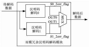
1.2.2 解码模块DMRH码解码模块如图 2所示,待解码的数据包括原码与两份校验码(分别记为P0和P1).
|
图 2 双模冗余汉明码解码电路 Fig. 2 Decode circuit for DMRH code |
依据汉明码的解码规则对校验码P0和原码做处理得到修正后数据OUT0和两位错误标志位S0_2err_flag;由校验码P1和原码得到修正后数据OUT1和两位错误标志位S1_2err_flag;MUX模块将依据S0_2err_flag和S1_2err_flag的值从OUT0和OUT1中选择正确的数据作为输出.
如表 2所示,记原码为D,当所存储的数据中出现一位翻转到两位翻转时,修正后的数据为OUT0和OUT1,两位翻转标志位为S0_2err_flag和S1_2err_ flag,表中共有9种不同的翻转类型.可以看到当两位翻转标志位为0时,解码得到的数据是正确的.因此,我们可以依据两位翻转标志位选择正确的数据作为解码模块的输出.但是,当两位翻转同时发生在数据位D内时,两位翻转标志位同时为1,此时,并不能从OUT0和OUT1内获得正确的数据作为解码模块的输出.
| 表 2 一位翻转与两位翻转输出结果分析 Tab. 2 Analysis for results of one-bit and two-bit upset |
为了进一步提高DMRH码的可靠性,本文依据版图分割技术对校验码与原码排序,消除了两位翻转同时发生在原码D内的情况.排序的基本原则为每两位原码之间至少要有一位校验码间隔.因此n与k还应该有关系为
| $ n \le 2k + 3. $ | (3) |
当高能粒子引起所存储的数据中发生两位翻转时,采用版图分割技术后,可能翻转的位置会出现以下3种情况:
a) 翻转的是P0内一位校验码和一位原码D;
b) 翻转的是P1内一位校验码和一位原码D;
c) 翻转的是两位校验码.
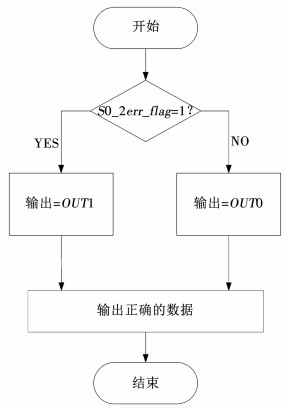
由表 2可知,a情况对应表内序号6的情况;b情况对应表内序号5的情况;c情况对应了表内序号4、7和8对应的情况.以上情况均可以通过S0_2err_flag和S1_2err_flag的值从OUT0和OUT1中选择出正确的数据作为DMRH码的输出.因此,本文所设计的MUX模块解码流程如图 3所示.
|
图 3 双模冗余汉明码解码流程图 Fig. 3 Flow chart for decoding of DMRH code |
由于版图分割技术消除了两位翻转同时出现在原码D内的情况,S0_2err_flag和S1_2err_flag不会同时为1.本文选用S0_2err_flag作为判定条件,当该值为1时,标志原码D与校验码P0内出现了两位错误,解码后得到的OUT0时错误的,此时应选择OUT1作为输出;同理,当该值为0时,选择OUT0作为输出.
本节在纠一检二汉明码的基础上设计了两位修正能力的DMRH码.接下来本文以原码n=8为例,实现该修正码.
2 双模冗余汉明码的实现 2.1 双模冗余汉明码编码电路的设计当原码为8位时(记为D0~D7),依据DMRH码的编码规则,需要10位校验码,其生成方式为
| $ \begin{array}{l} P0\left[ 0 \right] = {D_0}^ \wedge {D_1}^ \wedge {D_3}^ \wedge {D_4}^ \wedge {D_6}, \\ P0\left[ 1 \right] = {D_0}^ \wedge {D_2}^ \wedge {D_3}^ \wedge {D_5}^ \wedge {D_6}, \\ P0\left[ 2 \right] = {D_1}^ \wedge {D_2}^ \wedge {D_3}^ \wedge {D_7}, \\ P0\left[ 3 \right] = {D_4}^ \wedge {D_5}^ \wedge {D_6}^ \wedge {D_7}, \\ P0\left[ 4 \right] = {D_0}^ \wedge {D_1}^ \wedge {D_2}^ \wedge {D_4}^ \wedge {D_5}^ \wedge {D_6}, \\ P1\left[ 0 \right] = {D_0}^ \wedge {D_1}^ \wedge {D_3}^ \wedge {D_4}^ \wedge {D_6}, \\ P1\left[ 1 \right] = {D_0}^ \wedge {D_2}^ \wedge {D_3}^ \wedge {D_5}^ \wedge {D_6}, \\ P1\left[ 2 \right] = {D_1}^ \wedge {D_2}^ \wedge {D_3}^ \wedge {D_7}, \\ P1\left[ 3 \right] = {D_4}^ \wedge {D_5}^ \wedge {D_6}^ \wedge {D_7}, \\ P1\left[ 4 \right] = {D_0}^ \wedge {D_1}^ \wedge {D_2}^ \wedge {D_4}^ \wedge {D_5}^ \wedge {D_6}, \end{array} $ | (4) |
式中,^为异或运算.
P0[4]和P1[4]分别为D0~D7、P0[0]~P0[3]和P1[0]~P1[3]的异或运算的化简结果,使得原来的12位数据相异或减少到了6位相异或,有效减小了电路的延迟.
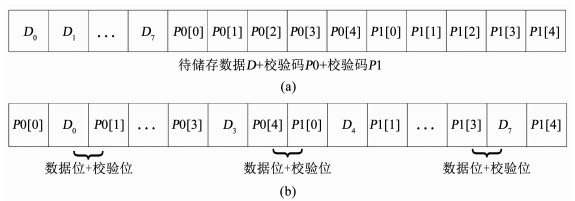
2.2 版图分割技术当输入的8位原码经过汉明码编码模块后,若按照图 4(a)的顺序存入存储单元,那么当高能粒子所引起的两位翻转全部出现在原码D内时,会影响解码后数据的正确性.
|
图 4 (a) 未采用版图分割技术的8位宽度字的版图结构; (b)采用版图分割技术的8位宽度字的版图结构 Fig. 4 (a) Architecture of eight-bit-word of memory without layout segmentation technology; (b) Architecture of eight-bit-word of memory with layout segmentation technology |
因此采用版图分割技术把原码D与校验码P0、P1排序,基本原则为每两位原码之间至少要有一位校验码间隔.使用版图分割法后,当原码为8时,版图结构如图 4(b)所示.
可以看到,当所存储数据在高能粒子影响下发生两位翻转时,有可能发生以下3种情况:
a) 一位原码和P0内一位校验位翻转;
b) P0内一位校验位与P1内一位校验位翻转;
c) P1内一位校验位和一位原码翻转.
由表 2可知,以上3种情况分别对应表内序号6、序号4和序号5代表的情况,可以结合两位错标志位的值从OUT0和OUT1选择正确的数据作为输出.
2.3 双模冗余汉明码解码电路的设计当需要从存储器中读取数据时,记存储器内读出的数据分别为D′、P0′和P1′,接下来需要按照汉明码的解码规则生成对应的状态码.
由读出的数据D′和P0′生成的状态码S0为
| $ \begin{array}{l} S0\left[ 0 \right] = P0'{\left[ 0 \right]^ \wedge }{{D'}_0}^ \wedge {{D'}_1}^ \wedge {{D'}_3}^ \wedge {{D'}_4}^ \wedge {{D'}_6}, \\ S0\left[ 1 \right] = P0'{\left[ 1 \right]^ \wedge }{{D'}_0}^ \wedge {{D'}_2}^ \wedge {{D'}_3}^ \wedge {{D'}_5}^ \wedge {{D'}_6}, \\ S0\left[ 2 \right] = P0'{\left[ 2 \right]^ \wedge }{{D'}_1}^ \wedge {{D'}_2}^ \wedge {{D'}_3}^ \wedge {{D'}_7}, \\ S0\left[ 3 \right] = P0'{\left[ 3 \right]^ \wedge }{{D'}_4}^ \wedge {{D'}_5}^ \wedge {{D'}_6}^ \wedge {{D'}_7}, \\ S0\left[ 4 \right] = P0'{\left[ 0 \right]^ \wedge }P0'{\left[ 1 \right]^ \wedge }P0'{\left[ 2 \right]^ \wedge }P0'{\left[ 3 \right]^ \wedge }\\ P0'{\left[ 4 \right]^ \wedge }{{D'}_0}^ \wedge {{D'}_1}^ \wedge {{D'}_2}^ \wedge {{D'}_3}^ \wedge {{D'}_4}^ \wedge {{D'}_5}^ \wedge {{D'}_6}^ \wedge {{D'}_7}. \end{array} $ | (5) |
在得到状态码S0的值后,依据汉明码解码规则可得翻转数据发生的位置,进而得到修正后的数据OUT0,同时可得两位错误标志位S0_2err_flag的值,其生成关系式为
| $ \begin{array}{l} S0\_2err\_flag = \left( {S0\left[ 4 \right] = 0\& \& S0\left[ {3:0} \right] \ne 4'b0000} \right)?\\ 1'b1:1'b0, \end{array} $ | (6) |
由读出的数据D′和P1′生成的状态码S1为
| $ \begin{array}{l} S1\left[ 0 \right] = P1'{\left[ 0 \right]^ \wedge }{{D'}_0}^ \wedge {{D'}_1}^ \wedge {{D'}_3}^ \wedge {{D'}_4}^ \wedge {{D'}_6}, \\ S1\left[ 1 \right] = P1'{\left[ 1 \right]^ \wedge }{{D'}_0}^ \wedge {{D'}_2}^ \wedge {{D'}_3}^ \wedge {{D'}_5}^ \wedge {{D'}_6}, \\ S1\left[ 2 \right] = P1'{\left[ 2 \right]^ \wedge }{{D'}_1}^ \wedge {{D'}_2}^ \wedge {{D'}_3}^ \wedge {{D'}_7}, \\ S1\left[ 3 \right] = P1'{\left[ 3 \right]^ \wedge }{{D'}_4}^ \wedge {{D'}_5}^ \wedge {{D'}_6}^ \wedge {{D'}_7}, \\ S1\left[ 4 \right] = P1'{\left[ 0 \right]^ \wedge }P1'{\left[ 1 \right]^ \wedge }P1'{\left[ 2 \right]^ \wedge }P1'{\left[ 3 \right]^ \wedge }\\ P1'{\left[ 4 \right]^ \wedge }{{D'}_0}^ \wedge {{D'}_1}^ \wedge {{D'}_2}^ \wedge {{D'}_3}^ \wedge {{D'}_4}^ \wedge {{D'}_5}^ \wedge {{D'}_6}^ \wedge {{D'}_7}. \end{array} $ | (7) |
在得到状态码S1的值后,依据汉明码解码规则可得翻转数据发生的位置,进而得到修正后的数据OUT1,同时可得两位错误标志位S1_2err_flag的值,其生成关系式为
| $ \begin{array}{l} S1\_2err\_flag = \left( {S1\left[ 4 \right] = 0\& \& S1\left[ {3:0} \right] \ne 4'b0000} \right)?\\ 1'b1:1'b0, \end{array} $ | (8) |
最后,依据S0_2err_flag和S1_2err_flag的值,从OUT0和OUT1里面选择出正确的数据作为输出,其具体流程如图 3所示.
在解码电路的设计中,本文通过分析存储器内发生两位翻转的情况,发现当翻转位置不同时,可以依据状态码中两位错误标志位的值来判定数据中发生翻转的位置,之后结合版图分割技术完成了解码电路算法的设计.
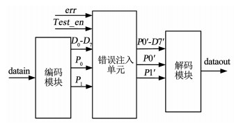
3 双模冗余汉明码的验证双模冗余汉明码测试系统的电路如图 5所示,为了验证它的纠错能力,添加了错误注入单元,用于向存储器中读出的数据中注入错误.在Test_en为0时,为正常工作模式,从存储器内读出的数据不作任何处理,直接交给解码模块解码.当Test_en为1时,进入测试模式,从存储器内读出的数据与测试变量err相异或,对数据进行修改.之后,再把修改后的数据交由解码模块解码.若解码后的数据与写入的数据一致,则认为加固方法有效,可以修正所存储数据中出现的两位错误.
|
图 5 双模冗余汉明码测试系统 Fig. 5 Test system of DMRH code |
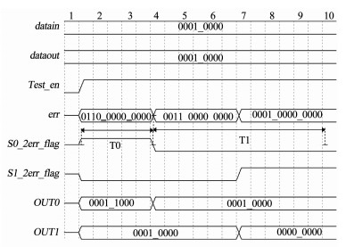
字长为8位的DMRH码的仿真结果如图 6所示,在Test_en有效后,通过err与加固后的数据相异或,向数据中注入错误.在时间段T0内,让(D3、P0[4])所存储的信息翻转,此时S0_2err_flag为1,选择OUT1作为输出,解码后得到的数据与原码相同.在时间段T1内,分别仿真了向(P0[4]、P1[0])与(P1[0]、D4)注入错误的情况,均得到预期的效果.最后遍历了所有可能的一位翻转与两位翻转的情况,仿真结果表明,DMRH能够修正数据中出现的错误,本文提出的加固方法是有效的.
|
图 6 双模冗余汉明码仿真结果 Fig. 6 Simulation results of DMRH code |
当工艺节点降低到130 nm时,大量试验数据表明其产生两位翻转的次数占总翻转次数的1%左右,三位翻转的次数占总翻转次数的0.1%左右[18].因此,相比于一位修正的汉明码,使用两位修正能力的DMRH码能够提高存储单元的可靠性.
4 双模冗余汉明码性能分析在本文中,共设计了三种DMRH码,分别对应字长为4、8和11,与其他修正码的面积、功耗和延迟参数对比如表 3所示.以汉明码为参考,字长为4、8和11的DMRH码的电路延迟分别是汉明码的85%、89%和96%,低于两位修正能力的BCH码.
| 表 3 修正电路的面积、功耗延迟参数列表 Tab. 3 Parameters of area, power, and delay for different ECC circuits |
本文提出了一种双模冗余汉明码,它能够抑制存储单元中出现的两位翻转.首先,对汉明码编码模块进行逻辑优化,有效减少了编码电路的延迟,再把该模块生成的校验码进行双模冗余处理,作为双模冗余汉明码编码模块的输出.之后依据汉明码解码规则分别对每份校验码与原码的组合进行处理,通过分析发现当两位翻转未同时发生在原码内时,可以依据两位错误标志位的值得到正确的输出.最后,采用版图分割技术有效抑制了两位原码同时翻转的情况,进一步提高了存储器的可靠性.与其他的两位错误修正码相比,本文提出的DMRH码具有较低的电路延迟.
| [1] |
RAJSUMAN R. Design and test of large embedded memories: An overview[J]. IEEE Design & Test of Computers, 2001, 18(3): 16. DOI:10.1109/54.922800 |
| [2] |
JIN Yi, HUAN Yuxiang, CHU Haoming, et al. TMR group coding method for optimized SEU and MBU tolerant memory design[C]//Proceedings of 2018 IEEE International Symposium on Circuits and Systems. Florence: IEEE, 2018: 1. DOI: 10.1109/iscas.2018.8351105
|
| [3] |
HUGHES H L, BENEDETTO J M. Radiation effects and hardening of MOS technology: devices and circuits[J]. IEEE Transactions on Nuclear Science, 2003, 50(3): 500. DOI:10.1109/TNS.2003.812928 |
| [4] |
BAUMANN R C. Radiation-induced soft errors in advanced semiconductor technologies[J]. IEEE Transactions on Device and Materials Reliability, 2005, 5(3): 305. DOI:10.1109/tdmr.2005.853449 |
| [5] |
GADLAGE M J, EATON P H, BENEDETTO J M, et al. Digital device error rate trends in advanced CMOS technologies[J]. IEEE Transactions on Nuclear Science, 2006, 53(6): 3466. DOI:10.1109/TNS.2006.886212 |
| [6] |
CARDARILLI G, BERTAZZONI S, SALMERI M, et al. Design of a fault tolerant solid state mass memory[J]. IEEE Transactions on Reliability, 1999, 52(4): 476. DOI:10.1109/DFTVS.1999.802897 |
| [7] |
GU Song, LIU Jie, BI Jinshun, et al. The impacts of heavy ion energy on single event upsets in SOI SRAMs[J]. IEEE Transactions on Nuclear Science, 2018, 65(5): 1091. DOI:10.1109/TNS.2018.2817574 |
| [8] |
HIRAO T, ITOH H, OKADA S, et al. Studies of single-event transient current induced in GaAs and Si diodes by energetic heavy ions[J]. Radiation Physics and Chemistry, 2001, 60(4/5): 269. DOI:10.1016/s0969-806x(00)00360-1 |
| [9] |
JIANG Jianwei, XU Yiran, ZHU Wenyi, et al. Quadruple cross-coupled latch-based 10T and 12T SRAM bit-cell designs for highly reliable terrestrial applications[J]. IEEE Transactions on Circuits and Systems Ⅰ: Regular Papers, 2019, 66(3): 967. DOI:10.1109/TCSI.2018.2872507 |
| [10] |
LACOE R C, OSBORN J V, KOGA R, et al. Application of hardness-by-design methodology to radiation-tolerant ASIC technologies[J]. IEEE Transactions on Nuclear Science, 2000, 47(6): 2334. DOI:10.1109/23.903774 |
| [11] |
TAUSCH H J, PUCHNER H. Analysis of hamming EDAC SRAMs using simplified birthday statistics[J]. IEEE Transactions on Nuclear Science, 2015, 62(4): 1771. DOI:10.1109/TNS.2015.2444272 |
| [12] |
MA Weijia, CUI Xiaole, LEE Chunglen. Enhanced error correction against multiple-bit-upset based on BCH code for SRAM[C]//Proceedings of 2013 IEEE 10th International Conference on ASIC. Shenzhen: IEEE, 2013: 1. DOI: 10.1109/ASICON.2013.6812015
|
| [13] |
NEUBERGER G, DE LIMA KASTENSMIDT F G, REIS R. An automatic technique for optimizing Reed-Solomon codes to improve fault tolerance in memories[J]. IEEE Design & Test of Computers, 2005, 22(1): 50. DOI:10.1109/MDT.2005.2 |
| [14] |
XIE Zhiyuan, LI Na, LI Lele. New decoder for triple-error-correcting binary BCH codes[C]// Proceedings of 2008 3rd IEEE Conference on Industrial Electronics and Applications. Singapore: IEEE, 2008: 1426. DOI: 10.1109/ICIEA.2008.4582754
|
| [15] |
LI Yueqian, SALEHI M. An efficient decoding algorithm for concatenated RS-convolutional codes[C]// Proceedings of 2009 43rd Annual Conference on Information Sciences and Systems. Baltimore, USA: IEEE, 2009: 411. DOI: 10.1109/CISS.2009.5054755
|
| [16] |
SÁNCHEZ-MACIÁN A, REVIRIEGO P, MAESTRO J A. Hamming SEC-DAED and extended Hamming SEC-DED-TAED codes through selective shortening and bit placement[J]. IEEE Transactions on Device and Materials Reliability, 2014, 14(1): 574. DOI:10.1109/TDMR.2012.2204753 |
| [17] |
WANG Xinsheng, XU Jianjun. Second hamming code used in radiation hardened communication environment[C]//Proceedings of 2016 Sixth International Conference on Instrumentation & Measurement, Computer, Communication and Control (IMCCC). Harbin: IEEE, 2016: 593. DOI: 10.1109/IMCCC.2016.141
|
| [18] |
MAIZ J, HARELAND S, ZHANG K, et al. Characterization of multi-bit soft error events in advanced SRAMs[C]//Proceedings of IEEE International Electron Devices Meeting. Washington DC: IEEE, 2003. DOI: 10.1109/IEDM.2003.1269335
|
 2020, Vol. 52


