2. 中国电力科学研究院有限公司,北京 100192
2. China Electric Power Research Institute, Beijing 100192, China
中国超、特高压输电线路建设已跨越江河、通信线、山谷等线路,大径厚比钢管更能满足输电塔大跨越方向发展需求,相较于只能按照固定规格生成的轧制钢管,焊接钢管几乎可制成连续变化的直径和厚度[1-2]。埋弧焊接具有焊接效率高、焊缝质量好、劳动条件较好的优点,在焊接圆钢管生产过程中得到广泛应用,但钢管焊接时局部高温加热产生热应力,冷却后不可避免产生焊接残余应力[3-4]。残余应力大小受焊接前的准备、焊接条件和多道焊缝中的焊道顺序等因素影响[5-6]。有限元法计算不同焊接工艺参数下的残余应力不但有较高的计算精度,而且可为焊接工艺的制定提供参考。
当钢管壁厚较大时,焊接工艺为多层多道次焊接,适宜的热源模型是实现焊接过程数值模拟的基本条件[7]。国内外学者相继提出了点热源模型、高斯热源模型、均匀体积热源模型、双椭球热源模型等[8-11],并逐渐应用到焊接数值模拟。杨俊芬等[12]采用均匀体热源模型对Q690埋弧焊接圆钢管焊接过程进行了1道次焊接成形模拟,得到了截面纵向残余应力分布模式。孟庆国等[13]应用双椭球热源模型进行了3维状态下低碳钢多层多道焊温度场的数值模拟,发现前一道次的预热作用可有助于后一道次进入准稳态。邓德安等[14]模拟了不锈钢厚板多道次焊接方法并研究了残余应力分布形式,结果表明焊接顺序对残余应力的大小和分布形状均影响显著。祁帅等[15]建立了X80管线钢三丝埋弧焊热-结构耦合模型,发现焊接速度的提高会引起焊后纵向残余应力的增大。Arif等[16]对低碳钢激光焊接过程进行了数值模拟,结果表明恒功率下,焊接速度的提高将降低高应力区的宽度。目前对于埋弧焊接高强(强度等级>460 MPa)圆钢管多层多道次焊接过程的研究相对不足,特别是焊接方向、焊接速度、道间温度等对残余应力分布的影响尚不十分明确。
本文采用ANSYS参数化语言,构造均匀体积热源模型模拟熔化极气体保护焊(GMAW)热源及构造双椭球热源模型模拟埋弧焊(SAW)热源,对高强埋弧焊接圆钢管3道次焊接过程进行了热-结构耦合瞬态分析。模型中定义了高强钢材随温度变化的物理力学参数,计算过程考虑了焊接工艺中的相变潜热,有限元模型可自动调整焊接过程中钢管与外界热交换的面积。通过有限元分析了焊接方向、焊接速度、道间温度对高强埋弧焊接圆钢管纵向残余应力分布的影响,对高强埋弧焊接圆钢管的焊接工艺提出优化建议。
1 有限元模型热-结构耦合瞬态有限元分析包括温度场和应力场模拟两部分,包含所需自由度的耦合单元类型,仅通过1次计算即可得到耦合场分析结果,适用于多个物理场各自的响应相互依赖且非线性程度较高的情况。
1.1 单元介绍焊接圆钢管采用20节点Solid226耦合单元模拟,包括X、Y、Z平动自由度和温度自由度。Solid226单元可模拟弹性、塑性、大应变、大挠度、应力硬化效应、预应力效应,为提高计算效率,采用缩减积分单元技术[17]。
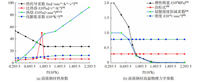
1.2 非线性材料属性热-结构耦合分析时需要定义室温(293.5 K)及以上所有焊接温度变化范围内的钢材物理性能参数。参考欧洲General rules-structural fire design[18]及文献[19-20],定义的高强钢材物理力学参数见图 1。
|
图 1 钢材物理性能参数 Fig. 1 Physical property parameters of steel |
钢材各温度下应力-应变曲线根据折算后的屈服应力采用理想弹塑性模型[19],见图 2。

|
图 2 钢材应力-应变曲线 Fig. 2 Stress-strain curves of steel |
焊接时焊缝金属存在固态相变、固液相变、蒸发3种相变,采用热焓法处理温度区间的相变潜热问题。热焓法将材料的潜在热量定义到焓中,热焓可表示为密度与比热容的乘积对温度的积分[21] :
| $ H\left( T \right) = \smallint \rho \left( T \right)c\left( T \right){\rm{d}}T $ | (1) |
式中:H(T)为热焓,ρ(T)为随温度变化的密度,c(T)为随温度变化的比热容,T为温度,单位为K,随温度变化的热焓见图 1(a)。
1.3 焊接工艺及热源模型高强埋弧焊接圆钢管由山东华安铁塔公司提供,厂方提供的焊接工艺如下:
1) 焊接坡口两侧保持干净,采用GMAW的焊接方法,采用直径1.2 mm的MG60-G-1焊丝、用80%Ar与20%CO2的保护气体完成第一道打底焊。
2) 用直径4.0 mm的H08MnMoA焊丝,焊剂为SJ101进行两道次SAW焊接,道间温度小于200 ℃。熔池宽度为9~11 mm,熔池深度8~9 mm,余高0~3 mm。埋弧焊焊接完成后尽量缓冷,24 h后再进行相关检测,各焊接道次参数见表 1。
| 表 1 焊接道次参数 Tab. 1 Parameters of welding passes |
3个焊接道次均采用同一焊接方向并根据焊接方式选取不同热源模型。GMAW热源采用均匀体积热源模型,热流密度为
| $ {q_0} = \frac{{\eta UI}}{{{V_{\rm{p}}}}} $ | (2) |
式中:q0为热流密度,U为焊接电压,I为焊接电流,根据表 1取U=20 V,I=140 A,η为焊接热效率取0.7[12],Vp表示均匀体积热源作用的体积,热源沿焊接方向的长度取8 mm,截面面积取第一道次焊缝截面面积[22]。
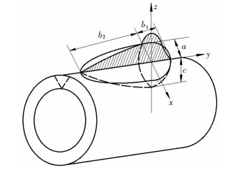
SAW热源采用双椭球热源模型,见图 3。双椭球热源模型前后两个1/4部分内部的热流密度q1、q2为:
| $ {q_1}(x, y, z) = \frac{{6\sqrt 3 {f_1}U\mathit{I}\eta }}{{a{b_1}c{\rm{ \mathsf{ π} }}\sqrt {\rm{ \mathsf{ π} }} }}\exp \left( { - \frac{{3{x^2}}}{{{a^2}}} - \frac{{3{y^2}}}{{b_1^2}} - \frac{{3{z^2}}}{{{c^2}}}} \right) $ | (3) |
| $ {q_2}(x, y, z) = \frac{{6\sqrt 3 {f_2}U\mathit{I}\eta }}{{a{b_2}c{\rm{ \mathsf{ π} }}\sqrt {\rm{ \mathsf{ π} }} }}\exp \left( { - \frac{{3{x^2}}}{{{a^2}}} - \frac{{3{y^2}}}{{b_2^2}} - \frac{{3{z^2}}}{{{c^2}}}} \right) $ | (4) |
|
图 3 双椭球热源模型 Fig. 3 Double ellipsoid heat source model |
式中:U、I根据表 1取U=24 V,I=530 A,焊接热效率η取0.7,f1=0.4、f2=1.6,b1=a取熔池宽度一半为4.5 mm,b2取熔池宽度2倍为18 mm、c取焊缝熔池深度9 mm[23]。
热源模型通过ANSYS函数定义功能直接输入热流密度,见图 4。

|
图 4 热源模型定义方式 Fig. 4 Definition method of heat source model |
焊接过程采用单元生死[17]方法模拟焊缝逐渐生长过程,开始计算前杀死焊缝处所有单元,计算过程中按焊接顺序依次激活被杀死的单元,每个荷载步间激活熔池纵向8 mm范围内单元。在不同荷载步间激活的单元附近建立局部坐标系,再选中热源模型作用范围内的节点,以生热率的形式施加热源载荷。
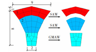
1.4 焊接圆钢管有限元模型有限元模型采用映射划分,钢管厚度方向网格尺寸为1 mm左右。根据3个焊接道次将焊缝划分为3层,焊缝尺寸及网格划分结果见图 5。
|
图 5 焊缝网格划分(mm) Fig. 5 Results of weld mesh generation (mm) |
对焊缝附近母材(钢管)的网格加密,随着距焊缝距离增大,网格尺寸由密变疏。网格疏密连接处通过接触MPC(多点约束方程)实现。MPC使用内部生成的约束方程在接触面上保持协调,但可以传递温度自由度,步骤如下:1)定义单元稀疏的表面为目标面(Targe170单元)及单元密集的表面为接触面(Conta174单元)。2)设置Conta174单元以下3个关键选项:模型自由度为X、Y、Z和T,计算约束为MPC多点约束方程,接触面为绑定接触。3)通过ESURF命令生成接触对。沿焊接方向(纵向)焊缝及其附近的网格尺寸为4 mm,远离焊缝区的单元网格尺寸划分为8~16 mm。
选中钢管焊接起始端(底部)节点,约束纵向位移,选中焊缝正对面1排节点,同时约束径向和环向位移,见图 6。

|
图 6 有限元模型网格划分和位移边界条件 Fig. 6 Mesh generation and displacement boundary conditions of finite element model |
热的传递包括热传导、对流和辐射3种基本形式。在熔焊的条件下由热源传热给焊件的热量主要是以辐射和对流为主,母材和焊条(焊丝)获得热能后,热的传播则是以热传导为主。辐射和对流可以采用综合换热系数ho表示[24] :
| $ {h_{\rm{o}}} = \left\{ \begin{array}{l} 0.066\;8T, \;\;\;\;\;0 < T \le 500℃\\ 0.231T - 82.1, \;\;\;\;T > 500℃ \end{array} \right. $ | (5) |
钢管的初始温度设定为293.5 K(20 ℃)。焊缝的生长将改变试件与空气的对流及热辐射面积,每一荷载步完成后,更新单元外表面,重新施加对流荷载,见图 7。

|
图 7 施加对流荷载后的有限元模型 Fig. 7 Finite element model with convection load |
焊接每一道次完成后冷却模型至473.5 K以内(道间温度低于200 ℃),全部焊接完成后冷却至室温293.5 K。
2 试验验证 2.1 试验概况设计制作了1组3根高强埋弧焊接圆钢管,试件规格和数量见表 2。
| 表 2 焊接圆钢管规格 Tab. 2 Specifications of welded circular steel tubes |
通过盲孔法[25]测试圆钢管跨中截面外表面的纵向残余应力分布模式,残余应力测试设备采用南京聚航科技有限公司生产的JHMK多点残余应力测量系统,由图 8中JHYC静态应变仪和JHZK钻孔装置以及静态应力测量软件组成。

|
图 8 残余应力测试设备 Fig. 8 Residual stress testing equipments |
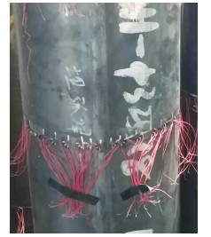
在焊缝附近应力梯度较大区域布置较密集的测点,随距焊缝距离的增加测点稀疏。应变计沿焊缝对称布置,盲孔横向最小间距大于5倍孔径(7.5 mm),纵向最小间距大于15倍孔径(22.5 mm),满足规范ASTM E837-20[26]的要求。在钢管焊缝一侧展开后的布置情况见图 9,测试完成后钢管见图 10。

|
图 9 测点布置 Fig. 9 Layout of measuring points |
|
图 10 测试完成的焊接圆钢管 Fig. 10 Welded circular steel tubes after testing |
图 11为埋弧焊接钢管测试结果,图中横坐标为焊缝两侧所在测点与焊缝形成的圆心角θ与π的比值,由图 11可见,纵向残余应力σr沿焊缝两侧分布基本对称,焊缝处为残余拉应力,接近屈服强度。随着距焊缝距离的增大,残余拉应力迅速降低并转变为压应力,转变区域位于焊缝两侧各15°范围内,表现出较大的应力梯度。继续增大,压应力再次转变为拉应力。

|
图 11 埋弧焊接钢管纵向残余应力测试结果 Fig. 11 Test results of longitudinal residual stress of submerged arc welded steel tubes |
计算工作站参数为Intel(R) Xeon(R) Gold 6234 CPU @ 3.30 GHz,内核16,逻辑处理器32,内存128 GB。分别对80、160、320、480 mm的钢管进行了数值模拟,有限元模型网格密度保持一致,计算时间分别为6 h 23 min、24 h 17 min、60 h 35 min、119 h 41 min。
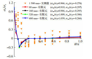
将纵向残余应力环向分布规律的计算值与实测值对比于图 12,有限元模型能够较为准确的反演纵向残余应力的不同分布模式。
|
图 12 纵向残余应力分布有限元模型计算值与试验值对比 Fig. 12 Comparison of longitudinal residual stress distribution between finite element model results and test results |
从图 12不同计算长度最大纵向残余应力(拉、压)计算值与实测值的对比知,随着计算长度的增大,最大纵向残余拉应力σrto略有增大而最大纵向残余压应力σrco无明显规律。当计算长度为160 mm时,相较于实测值,最大纵向残余拉应力误差为2.07%,最大纵向残余压应力误差为7.68%。综合考虑计算精度和计算耗时的因素,以160 mm为计算长度进行拓展研究,纵向残余应力分布见图 13。

|
图 13 160 mm钢管纵向残余应力分布(MPa) Fig. 13 Longitudinal residual stress distribution of 160 mm steel tube (MPa) |
根据厂家提供的标准生产工艺,取表 1中参数的中位数,计算长度为160 mm,各焊接道次的方向均为由下至上。各焊接道次温度场分布见图 14,各道次最大焊接温度均出现在最终落焊点位置处,第一道GMAW打底焊温度最低,热影响区域长度最小。3个道次焊接完成时瞬态温度依次为958.54、1 320.49、1 322.15 K,热影响区域宽度在15°以内。

|
图 14 各焊接道次温度分布(K) Fig. 14 Temperature distribution of each welding pass (K) |
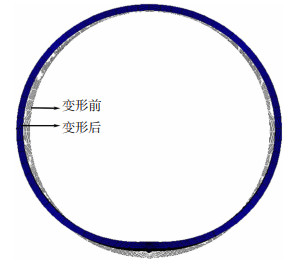
焊后残余变形见图 15,焊缝附近发生了收缩而焊缝两侧钢管发生了外胀。焊接时局部高温的焊缝区膨胀受到临近低温钢材约束产生压应力,使得热塑状态的焊缝产生塑性压缩变形。在焊后冷却过程中,钢材因已有的塑性变形不能恢复原来长度。收缩变形的大小与冷却速度相关,道间温度越高则冷却速度越慢,导致收缩变形增大[27]。
|
图 15 焊接残余变形(变形放大20倍) Fig. 15 Welding residual deformation (deformation magnified by a factor of 20) |
为研究各道次焊接方向对纵向残余应力的影响,4种焊接方向工况下纵向残余应力分布见图 16,最大纵向残余拉应力σrto大小关系为工况一<工况二<工况四<工况三,最大纵向残余压应力σrco大小关系为工况二<工况三<工况四<工况一,即工况一最大纵向残余拉应力σrto最小,工况二最大纵向残余压应力σrco最小。工况二最大纵向残余拉应力比工况一高9.12%,最大纵向残余压应力比工况一低29.83%,综合考虑残余压、拉应力最小焊接方向工况二最优。故焊接时第一和第三道次焊接方向相同而第二道次应反向。

|
图 16 焊接方向对纵向残余应力的影响 Fig. 16 Influence of welding direction on longitudinal residual stress |
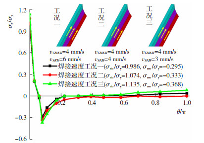
为研究各个焊接道次焊接速度对纵向残余应力的影响,3种焊接速度工况计算结果见图 17。
|
图 17 焊接速度对纵向残余应力的影响 Fig. 17 Influence of welding speed on longitudinal residual stress |
图 17中vGMAW表示GMAW焊接速度,vSAW表示SAW焊接速度,焊接速度的改变对应于ANSYS中每个荷载步瞬态分析的计算时间,由图 17知,焊接速度工况一最大纵向残余拉应力σrto和最大纵向残余压应力σrco均最小,为最优焊接速度工况。本文焊接速度建议值为第一道次4 mm/s,第二、三道次6 mm/s。
3.3.3 道间温度根据1.3节焊接工艺说明,道间温度需低于473.5 K(200 ℃),道间温度为母材在下一焊道施焊之前的最高瞬时温度,即图 18中每道次焊接完成后的最高温度。为研究道间温度对纵向残余应力的影响,3种道间温度工况计算结果对比见图 18,相较于工况一,工况二仅第二道焊接完成后最高瞬时温度增大了75 K,最大纵向残余拉应力σrto增大了12.17%,最大纵向残余压应力σrco增大了1.36%。因此第二道焊接完后道间温度的增大会导致焊接残余应力增大。相较于工况二,工况三仅第一道焊接完成后最高瞬时温度增大了35 K,则最大纵向残余拉应力σrto增大了1.18%,最大纵向残余压应力σrco增大了10.03%。因此第一道焊接完后道间温度的增大会导致焊接残余应力增大。道间温度的提高会导致焊接残余应力提高,焊接时冷却时间的增加使得道间温度降低,但会增加时间成本。为使焊接残余应力最小,在冷却时间成本可控范围内道间温度应控制在最低范围。

|
图 18 道间温度对纵向残余应力影响 Fig. 18 Influence of interpass temperature on longitudinal residual stress |
对高强埋弧焊接圆钢管3道次焊接过程进行了数值模拟,分析了焊接方向、焊接速度、道间温度对最大纵向残余应力的影响,得到如下结论:
1) 数值模拟结果与试验测定结果对比表明,本文有限元模拟方法可以模拟高强埋弧焊接圆钢管焊接过程并对焊接纵向残余应力的大小进行预测。
2) 第一和第三道次焊接方向相同而第二道次反向为最优焊接方向,与3个焊接道次同向相比,虽纵向残余拉应力大9.12%,但纵向残余压应力小29.83%。
3) 第一道次焊接速度为4 mm/s,第二、三道次焊接速度为6 mm/s时,焊后最大纵向残余应力最小。
4) 道间温度提高后最大纵向残余应力增大。第一道焊接完成后道间温度每增加1 K,最大纵向残余拉应力提高0.03%,最大纵向残余压应力提高0.28%。第二道焊接完成后道间温度每增加1 K,最大纵向残余拉应力提高0.16%,最大纵向残余压应力提高0.02%。
| [1] |
刘海锋, 边奇, 扶达鸿, 等. 大跨越输电塔主材加劲钢管残余应力分布特点研究[J]. 建筑结构, 2020, 50(23): 58. LIU Haifeng, BIAN Qi, FU Dahong, et al. Study on residual stress distribution characteristics of stiffened steel pipe of the chord member in large span transmission tower[J]. Building Structure, 2020, 50(23): 58. DOI:10.19701/j.jzjg.2020.23.010 |
| [2] |
闫西峰. 不同成型方式圆钢管轴心受压构件整体稳定性能研究[D]. 西安: 西安建筑科技大学, 2017 YAN Xifeng. Overall buckling study on different formed steel tubular members under axial compression[D]. Xi'an: Xi'an University of Architecture and Technology, 2017 |
| [3] |
麻宏强, 贺斌贤, 刘叶敏, 等. 钎焊接头对铝制板翅结构热应力影响规律[J]. 哈尔滨工业大学学报, 2019, 51(2): 173. MA Hongqiang, HE Binxian, LIU Yemin, et al. Influence of brazed joints on stress of plate-fin structures in LNG heat exchanger[J]. Journal of Harbin Institute of Technology, 2019, 51(2): 173. |
| [4] |
王佳, 刘玉擎, 黄李骥. 高强度钢加劲板焊接残余应力测试及分析[J]. 工程力学, 2016, 33(6): 243. WANG Jia, LIU Yuqing, HUANG Liji. Experimental and numerical analysis of welding residual stress in high strength stiffened plates[J]. Engineering Mechanics, 2016, 33(6): 243. DOI:10.6052/j.issn.1000-4750.2014.11.0995 |
| [5] |
LEGGATT R H. Residual stresses in welded structures[J]. International Journal of Pressure Vessels and Piping, 2008(85): 144. DOI:10.1016/j.ijpvp.2007.10.004 |
| [6] |
谢超. 钢桥典型构造焊接残余应力有限元分析[D]. 成都: 西南交通大学, 2017 XIE Chao. Finite element analysis of welding residual stress of typical steel bridge structures[D]. Chengdu: Southwest Jiaotong University, 2017 |
| [7] |
谷京晨, 童莉葛, 黎磊, 等. 焊接数值模拟中热源的选用原则[J]. 材料导报, 2014, 28(1): 143. GU Jingchen, TONG Lige, LI Lei, et al. Selection criteria of heat source model on the welding numerical simulation[J]. Materials Review, 2014, 28(1): 143. |
| [8] |
ROSENTHAL D. Mathematical theory of heat distribution during welding and cutting[J]. Welding Journal, 1941, 20(5): 220. |
| [9] |
PAVELIC V, TANBAKUCHI R, UYEHARA O, et al. Experimental and computed temperature histories in gas tungsten-arc welding of thin plates[J]. Welding Journal, 1969, 48(7): 295. |
| [10] |
GOLDAK J, CHAKRAVARTI A, BIBBY M. A new finite element model for welding heat sources[J]. Metallurgical and Materials Transactions B, 1984, 15(2): 299. |
| [11] |
GOLDAK J, BIBBY M, MOORE J, et al. Computer modeling of heat flow in welds[J]. Metallurgical and Materials Transactions B, 1986, 17(3): 587. DOI:10.1007/BF02670226 |
| [12] |
杨俊芬, 李渊, 彭奕亮. Q690高强钢管焊接残余应力数值模拟[J]. 工程力学, 2014, 31(10): 108. YANG Junfen, LI Yuan, PENG Yiliang. Numerical analysis on welding residual stress in Q690 high-strength steel pipe[J]. Engineering Mechanics, 2014, 31(10): 108. DOI:10.6052/j.issn.1000-4750.2013.04.0365 |
| [13] |
孟庆国, 方洪渊, 杨建国, 等. 多道焊温度场数值模拟及其分布规律的研究[J]. 机械工程学报, 2005(1): 128. MENG Qingguo, FANG Hongyuan, YANG Jianguo, et al. Numerical simulation of multi-pass welding's temperature field and study of temperature distribution rules[J]. Chinese Journal of Mechanical Engineering, 2005(1): 128. |
| [14] |
邓德安, 清岛祥一. 焊接顺序对厚板焊接残余应力分布的影响[J]. 焊接学报, 2011, 32(12): 55. DENG Dean, SHOICHI K. Influence of welding sequence on welding residual stress distribution in thick plate joint[J]. Transactions of the China Welding Institution, 2011, 32(12): 55. |
| [15] |
祁帅, 严春妍, 史志丹, 等. X80管线钢三丝埋弧焊纵向残余应力数值模拟[J]. 电焊机, 2015, 45(4): 153. QI Shuai, YAN Chunyan, SHI Zhidan, et al. Numerical simulation of the longitudinal residual stress of X80 pipeline steel in triple-wire submerged arc welding[J]. Electric Welding Machine, 2015, 45(4): 153. DOI:10.7512/j.issn.1001-2303.2015.04.34 |
| [16] |
ARIF A F M, AL-OMARI A S, YILBAS B S, et al. Thermal stress analysis of spiral laser-welded tube[J]. Journal of Materials Processing Technology, 2011(211): 675. DOI:10.1016/j.jmatprotec.2010.12.002 |
| [17] |
ANSYS user's manual for version 17.2[Z]. Canonsburg: ANSYS Inc, 2016
|
| [18] |
Eurocode 3: design of steel structures-part 1.2: general rules-structural fire design: EN 1993-1-2 [S]. Brussels: CEN, 2005
|
| [19] |
马学周. Q460高强钢多层多道焊残余应力数值计算[D]. 镇江: 江苏科技大学, 2014 MA Xuezhou. Numerical analysis of residual stress in multi-pass welding of Q460 high strength steel[D]. Zhenjiang: Jiangsu University of Science and Technology, 2014 |
| [20] |
WANG W Y, LI G Q, GE Y. Residual stress study on welded section of high strength Q460 steel after fire exposure[J]. Advanced Steel Construction, 2015, 11(2): 151. |
| [21] |
许波, 王恪典, 李雪芝, 等. 焊接数值计算中几相变潜热处理方法[J]. 热加工工艺, 2020, 49(3): 9. XU Bo, WANG Kedian, LI Xuezhi, et al. Several treatment methods of latent heat of phase change in numerical calculation of welding[J]. Hot Working Technology, 2020, 49(3): 9. DOI:10.14158/j.cnki.1001-3814.20183249 |
| [22] |
李红涛, 宋绪丁. 不同热源模型对Q345中厚板焊接温度场的影响[J]. 热加工工艺, 2017, 46(23): 206. LI Hongtao, SONG Xuding. Influence of different heat source models on welding temperature field of Q345 medium plate[J]. Hot Working Technology, 2017, 46(23): 206. DOI:10.14158/j.cnki.1001-3814.2017.23.056 |
| [23] |
莫春立, 钱百年, 国旭明, 等. 焊接热源计算模式的研究进展[J]. 焊接学报, 2001(3): 96. MO Chunli, QIAN Bainian, GUO Xuming, et al. The development of models about welding heat sources' calculation[J]. Transactions of the China Welding Institution, 2001(3): 96. |
| [24] |
AKBARI D, SATTARI-FAR I. Effect of the welding heat input on residual stresses in butt-welds of dissimilar pipe joints[J]. International Journal of Pressure Vessels and Piping, 2009, 86(11): 772. DOI:10.1016/j.ijpvp.2009.07.005 |
| [25] |
YAN Xifeng, YANG Chao. Experimental research and analysis on residual stress distribution of circular steel tubes with different processing techniques[J]. Thin-Walled Structures, 2019(144): 1. DOI:10.1016/j.tws.2019.106268 |
| [26] |
ASTM International. Standard test method for determining residual stresses by the hole-drilling strain gage method: ASTM E837-20[S]. West Conshohocken: ASTM, 2020
|
| [27] |
姚谏, 夏志斌. 钢结构原理与设计[M]. 北京: 中国建筑工业出版社, 2011. YAO Qian, XIA Zhibin. Steel structure principle and design[M]. Beijing: Chinese Architecture and Building Press, 2011. |
 2022, Vol. 54


